ELEGOO UNO R3 Most Complete Starter Kit: lesson by lesson, simulated
The four parts of the kit’s V2.0 tutorial, lesson by lesson, each one a circuit that runs in your browser with the kit’s parts on the kit’s pins. Use it beside your manual, or to keep going while a part is missing.
39 of the 44 lessons with a circuit run here, 5 of them with a change we name, 5 coming soon, 4 setup lessons need no circuit.
Not affiliated with ELEGOO. Lesson titles are referenced so you can follow along.
Every lesson in the kit’s order
Lesson numbers and titles follow tutorial V2.0, from the download dated 2023.05.08 (older boxes ship the V1.0 tutorial, which numbers its lessons differently). Each circuit uses the kit’s parts on the pins the lesson uses.
- 1.1
Packing List
No circuitWhat is in the box. Every part the lessons use is in the editor’s parts panel.
- 1.2
First Look Arduino
No circuitA tour of the Uno board. Hover any pin on the canvas to see its name.
- 1.3
For Windows Setting up development environment
No circuitInstalling the IDE and drivers on Windows. Not needed here: everything runs in the browser.
- 1.4
For Mac and Ubuntu Building a Developed Environment
No circuitThe same setup on a Mac or on Linux. Not needed here either.
- 1.5
Blink and Add Libraries
Runs hereThe LED on pin 13 blinking once a second. The kit’s libraries are already built in.
- 2.1
LED
Runs hereAn LED and a resistor on the 5 V pin, no code. Try 1k and 10k in place of 220 ohm.
- 2.2
RGB LED
Runs hereRed on pin 6, green on 5, blue on 3, fading from color to color.
- 2.3
Digital Inputs
Runs hereA button on pin 9 turns the LED on pin 5 on, a button on pin 8 turns it off.
- 2.4
Serial Monitor
Runs hereTalking to the board through the serial monitor, the tool you will use in every later lesson.
- 2.5
Active Buzzer
Runs hereAn active buzzer on pin 12, beeping fast and then slow.
- 2.6
Passive Buzzer
Runs hereA passive buzzer on pin 8 plays a scale with tone().
- 2.7
Tilt Ball Switch
Runs hereTip the ball switch on pin 2 and the LED on pin 13 lights.
- 2.8
Servo
Runs hereA micro servo on pin 9 moving to set angles and sweeping back.
- 2.9
Ultrasonic Sensor Module
Runs hereAn HC-SR04, TRIG on 12 and ECHO on 11, measuring distance in centimeters.
- 2.10
Membrane Switch Module
Runs hereA 4x4 keypad, rows on pins 9 to 6 and columns on 5 to 2, printing each key.
- 2.11
DHT11 Temperature and Humidity Sensor
Runs hereA DHT11 on pin 2 reading temperature and humidity.
- 2.12
Analog Joystick Module
Runs hereX on A0, Y on A1, the switch on pin 2.
- 2.13
IR Receiver Module
Runs hereAn IR receiver on pin 11 decoding the remote.
- 2.14
MAX7219 LED Dot Matrix Module
Runs hereAn 8x8 matrix on a MAX7219, DIN 12, CLK 10 and CS 11, drawing faces.
- 2.15
Gyro (MPU-6050 Module)
Runs hereAn MPU-6050 on the I2C pins, printing its raw acceleration and rotation.
Some boxes ship a QMI-8658 board for this lesson instead; that chip is not simulated yet.
- 2.16
HC-SR501 PIR Sensor
Runs hereA motion sensor on pin 7 lights the LED on pin 13.
- 2.17
Water Level Detection Sensor Module
Runs hereA water level sensor on A0, sorted into dry, low, half and full.
- 2.18
Real Time Clock Module
Runs hereA DS1307 clock on A4 and A5 keeping the date and time.
- 2.19
Sound Sensor Module
Runs hereA sound sensor with its analog output on A0 and its digital output on pin 3.
- 2.20
RC522 RFID Module
Runs hereAn RC522 reader, SS on 10 and RST on 9, printing each card’s ID.
- 2.21
LCD Display
Runs hereA 16x2 LCD on pins 7 to 12.
The contrast knob is left out: the simulated display is always readable, so V0 goes to ground.
- 2.22
Eight LED with 74HC595
Runs hereEight LEDs on a shift register: data 12, clock 9, latch 11.
- 2.23
DC Motors
Runs hereAn L293D on pins 5, 3 and 4 driving a motor both ways.
The motor runs from the Uno’s 5 V here; on the bench the lesson powers it from the breadboard power module.
- 2.24
Stepper Motor
Runs hereA 28BYJ-48 on pins 8 to 11, one turn each way.
- 2.25
EEPROM
Runs hereSaving numbers in the Uno’s EEPROM so they survive a reset.
- 3.1
Thermometer
Runs hereA thermistor on A0, the temperature on the LCD.
The contrast knob is left out: the simulated display is always readable, so V0 goes to ground.
- 3.2
74HC595 And Segment Display
Runs hereA digit counting down through a 74HC595 on pins 2, 4 and 3.
One 220 ohm resistor on the common pin stands in for a resistor on every segment.
- 3.3
The Serial Monitor
Runs hereLighting the shift register’s LEDs by typing into the serial monitor.
- 3.4
Photocell
Runs hereA photocell on A0 drives a bar of eight LEDs.
- 3.5
Four Digit Seven Segment Display
Runs hereFour digits on a 74HC595, pins 8, 10 and 9.
- 3.6
Relay
Runs hereA relay driven by the L293D switches the motor.
The motor runs from the Uno’s 5 V here; on the bench the lesson powers it from the breadboard power module.
- 3.7
Controlling a Stepper Motor With Remote
Runs hereThe remote’s VOL+ and VOL- turn the stepper.
- 3.8
Controlling a Stepper Motor With Rotary Encoder
Runs hereA rotary encoder on pins 2, 3 and 4 steers the stepper click for click.
- 3.9
Creating Timer
Runs, with a changeA countdown timer on a four-digit display, set with buttons on A3 and 6 and started with A1.
The buzzer runs straight from A2 and the LED on A0 has no 10k pull-up; the kit adds an 8050 transistor and that resistor for more drive.
- 4.1
Dice
Runs, with a changeShake the tilt switch and an 8x8 matrix rolls a die.
The kit builds this on its ALL IN ONE Sensor Shield. Mokxi has no model of that shield yet, so the same parts are wired on a breadboard to the same pins the shield uses.
- 4.2
Greedy Snake
Coming soonA snake game on the matrix, steered by tilting the board.
Built on the kit’s ALL IN ONE Sensor Shield, which Mokxi does not model yet. Coming soon.
- 4.3
Memory Arithmetic Game
Coming soonA mental arithmetic game with the shield’s buttons and display.
Built on the kit’s ALL IN ONE Sensor Shield, which Mokxi does not model yet. Coming soon.
- 4.4
Fruit Forecast
Coming soonA catching game on the matrix.
Built on the kit’s ALL IN ONE Sensor Shield, which Mokxi does not model yet. Coming soon.
- 4.5
Multifunctional alarm clock
Coming soonA clock with an alarm on the shield’s display.
Built on the kit’s ALL IN ONE Sensor Shield, which Mokxi does not model yet. Coming soon.
- 4.6
Ultrasonic Ranging
Runs, with a changeHold a button and the distance in front of the sensor appears on the LCD.
The kit builds this on its ALL IN ONE Sensor Shield. Mokxi has no model of that shield yet, so the same parts are wired on a breadboard to the same pins the shield uses.
- 4.7
RFID Time Clock
Coming soonClocking in with RFID cards, the time on the LCD.
Built on the kit’s ALL IN ONE Sensor Shield, which Mokxi does not model yet. Coming soon.
- 4.8
Infrared Remote Switch Light
Runs, with a changeA servo arm flips a light switch when you press 1 or 2 on the remote.
The kit builds this on its ALL IN ONE Sensor Shield. Mokxi has no model of that shield yet, so the same parts are wired on a breadboard to the same pins the shield uses.
- 4.9
Body-sensing Nightlight
Runs, with a changeA motion sensor turns on an RGB night light for 20 seconds.
The kit builds this on its ALL IN ONE Sensor Shield. Mokxi has no model of that shield yet, so the same parts are wired on a breadboard to the same pins the shield uses.
Lesson list and pins read from ELEGOO’s tutorial download page. The explanations on this page are our own.
A link and a QR code for this page
Print either one beside a lesson, or tape it inside the box lid. Both open this page.
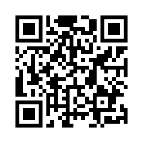
mokxi.com/k/elegoo-complete
The code is black on white with a quiet border, so it prints and scans at any size from 2 cm up.
Download the QR code (SVG)Make kits? See what we offer kit makers.
Questions about this page
Is this made by ELEGOO?
No. Mokxi is independent and is not affiliated with ELEGOO. The page follows the kit’s lessons so you can use the two side by side; the circuits, sketches and explanations are Mokxi’s own.
Do I need the kit?
No. Every lesson that runs here runs in the browser, so you can try them before you buy a kit, or keep going while a part is missing or broken.
Is the code the same as in my manual?
The pins and the parts are the same, and the sketches use the same libraries where the kit does. The code itself is written for this page, with comments that explain each step, so it will not match the manual line for line.
What do "with a change" and "coming soon" mean?
A lesson marked "with a change" runs, but something differs from the kit, and the note under it says exactly what. "Coming soon" means we cannot simulate that lesson yet, and the note says why. We do not mark a lesson as running unless it does.
Is it free?
Yes. Every lesson on this page opens with no account. A free account saves your own copies of the circuits.
Other kits
Companion pages for more starter kits.
Start at lesson one
Every lesson opens in the editor with no account and nothing to install. Run it, change a number, run it again.