Breadboard power supply, MB102
The Elegoo kit power module: a 9 V battery on its jack, 5 V or 3.3 V on each pair of rails by jumper.
- 8 pins
- 3 settings
- In 1 project
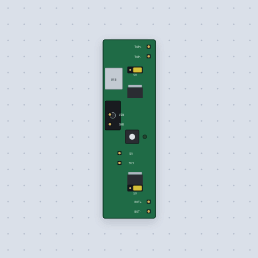
The Breadboard power supply, MB102 in brief
What it is, and every setting the properties panel gives it.
The MB102 is the small green starter kit board that plugs into both pairs of rails at the end of a breadboard. It takes a 9 volt battery or a 6.5 to 12 volt adapter on its barrel jack, or 5 volts from its USB socket, and a jumper on each side puts 5 V, 3.3 V or nothing on that pair of rails. Mokxi models the two real regulators: the jack feeds an AMS1117-5.0 and the 5 volt net feeds an AMS1117-3.3, with about a volt of dropout and a current limit near an amp, so a 9 volt battery gives a solid 5 volts, four fresh AA cells just manage it at a light load, and three leave both rails short. Clicking the module works its power switch. Wired with an Arduino, share the ground and nothing else: joining the module’s 5 V to the Uno’s 5V pin sets two supplies fighting over one rail, and leaving out the ground wire makes a servo twitch. Heat and reversed polarity on the jack are not modeled.
- Family
- Power and wiring
- Pins
- 8
- top
- 5V (or 3.3V, off)
- bottom
- 5V (or 3.3V, off)
- usb
- false
8 pins
Named as the editor names them, so a wire lands where you expect it.
How to use the MB102 power module with an Arduino
Stand the module on the left end of the breadboard with TOP+ in the first hole of the top red rail, so all four rail pins land in their rails. Feed the jack from a 9 V battery, set the top jumper to 5V and the bottom one to 3.3V, and put the servo on the top rails.
The Uno shares only its ground and the servo’s signal on pin 9. Its 5V pin stays off the module’s rails, so the two supplies never fight. Click the module while it runs and both rails go dead. Forget the ground wire instead and the servo’s signal has no reference, so it twitches or does nothing.
for (int angle = 0; angle <= 180; angle += 45) {
  arm.write(angle);
  delay(400);
  long millivolts = (long)analogRead(A0) * 5000 / 1023;
  Serial.println(millivolts);
}What is true about the Breadboard power supply, MB102, here
In its help article’s own words: what the simulation gets right, and where it stops.
Modeled
Two real regulators. The jack feeds an AMS1117-5.0 and the 5 V net feeds an AMS1117-3.3, both the bench's regulator model with the AMS1117 card: about a volt of dropout, an amp of current limit, 5 mA of bias. A 9 V battery gives a solid 5 V; four fresh AA cells (6.4 V) just manage it at a light load; three cells leave both rails short, because the 3.3 V side runs off the 5 V net.
The loads add up. Everything on the 3.3 V rail comes through the 5 V regulator too, and a short on either rail is held to about an amp.
The battery's own resistance. A 9 V battery is a volt and a half of sag at an amp, so heavy loads on a battery-fed module drop out sooner than on a wall supply.
USB puts 5 V from the socket on the 5 V net, and the 5 V regulator has nothing to do.
The switch cuts both the jack and USB, and the rails go dead.
Not modeled
Heat: the 5 V regulator turning 9 V into 5 V at 300 mA burns 1.2 W, and a long stall gets the SOT-223 too hot to touch, which here never happens. Reversed polarity on the jack, which on most copies destroys the regulators. The power LED is drawn as its current only, and the 3.3 V net carries a third of a milliamp of bleed so it always has a load.
From Breadboard power supply (MB102), in full.
See the Breadboard power supply, MB102 in a project
One built-in project uses it. It opens in the editor, already wired.
The boards it is shown on
This board has a built-in project with the Breadboard power supply, MB102 in it.
The rest of the bench
Every one of these is drawn and simulated the same way.
Wire up the Breadboard power supply, MB102
Open the editor and push it into the breadboard. It is free, and it runs on your own machine.