RTD converter, MAX31865
A PT100 platinum probe as a 15-bit resistance ratio over SPI mode 1, with fault thresholds.
- 7 pins
- 3 settings
- In 1 project
- In 1 lesson
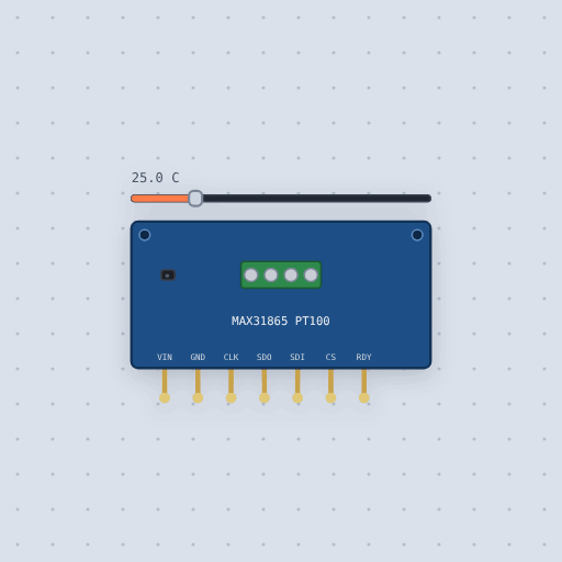
The RTD converter, MAX31865 in brief
What it is, and every setting the properties panel gives it.
The MAX31865 is a converter that reads a PT100 or PT1000 platinum RTD as a 15-bit resistance ratio over SPI. A platinum RTD is the most accurate common thermometer: its resistance rises steadily with temperature, 100 ohms at 0 C for a PT100. The chip measures the probe against a precise reference resistor on the board. The model has properties for the RTD's temperature, the nominal resistance at 0 C (100 or 1000) and the board's reference resistor (430 or 4300). It speaks SPI in mode 1 or 3, with a configuration register, an RTD ratio register whose low bit is a fault flag, threshold registers and a fault status register. Adafruit's library, shipped as Adafruit_MAX31865.h, drives it. The model leaves out the wire count's effect on the reading, the fault detection cycle's voltage tests, and mains noise. It does not simulate an open probe reporting a high-threshold and REFIN- fault.
- Family
- Sensors
- Pins
- 7
- temperature
- 25
- nominal
- 100
- reference
- 430
7 pins
Named as the editor names them, so a wire lands where you expect it.
How to use the MAX31865 with an Arduino Uno
The example project, Kiln and bath probes, uses a K-type thermocouple on a MAX31855 for the kiln and a PT100 probe on a MAX31865 for the glaze bath beside it, where a tenth of a degree matters. The thermocouple reaches far hotter than an RTD, and the RTD is far more exact. The MAX31865 is wired to the Uno as follows: VIN to 5 V, GND to GND, CLK to pin 13, SDO to pin 12, SDI to pin 11 and CS to pin 10.
The sketch includes SPI.h and Adafruit_MAX31865.h, creates a MAX31865 object with CS on pin 10, and calls begin with MAX31865_2WIRE in setup. The loop reads the bath temperature with bath.temperature(100.0, 430.0), passing the PT100's nominal resistance and the 430 ohm reference resistor. It prints the kiln thermocouple, the MAX31855's own board temperature, and the bath RTD each pass, then waits 500 ms.
With default settings, the serial monitor printed: "Kiln and bath probes", "kiln 0 C board 0.0 C bath 62.5 C", "kiln 850 C board 24.0 C bath 62.5 C". The bath value comes from the RTD temperature setting, the kiln value from the thermocouple slider, and the board value from the MAX31855's cold junction reading.
After changing the temperature setting to 535, the serial monitor printed: "kiln 0 C board 0.0 C bath 535.0 C", "kiln 850 C board 24.0 C bath 535.0 C". Only the bath number followed the new RTD temperature; the kiln and board readings stayed the same. You can also drag the thermocouple slider past 1000 C and watch the sketch call the kiln ready.
// Kiln and bath probes: a K-type thermocouple on a MAX31855 for the kiln,
// which runs to well over 1000 C, and a PT100 platinum probe on a MAX31865
// for the glaze bath beside it, where a tenth of a degree matters.
//
//   MAX31865  CLK -> 13   SDO -> 12   SDI -> 11   CS -> 10
//   MAX31855  CLK -> 7    CS -> 6     DO -> 5
//
// A thermocouple reaches far hotter than an RTD; an RTD is far more exact.
// The MAX31855 also reads its own board's temperature, the cold junction.
//
// Things to try. Drag the thermocouple slider past 1000 C and watch the
// sketch call the kiln ready. Drag the RTD slider.

#include <SPI.h>
#include "Adafruit_MAX31855.h"
#include <Adafruit_MAX31865.h>

Adafruit_MAX31855 kiln(7, 6, 5);  // CLK, CS, DO
Adafruit_MAX31865 bath(10);       // CS, on the SPI pins

void setup() {
  Serial.begin(9600);
  kiln.begin();
  bath.begin(MAX31865_2WIRE);
  Serial.println("Kiln and bath probes");
}

void loop() {
  double k = kiln.readCelsius();
  float b = bath.temperature(100.0, 430.0);
  Serial.print("kiln ");
  if (isnan(k)) {
    Serial.print("fault");
  } else {
    Serial.print(k, 0);
    Serial.print(" C");
  }
  Serial.print("  board ");
  Serial.print(kiln.readInternal(), 1);
  Serial.print(" C  bath ");
  Serial.print(b, 1);
  Serial.println(" C");
  if (!isnan(k) && k >= 1000) {
    Serial.println("Kiln at temperature");
  }
Common RTD converter, MAX31865 errors and fixes
Questions and answers
what is the max31865
It is a converter that reads a PT100 or PT1000 platinum RTD as a 15-bit resistance ratio over SPI, with fault thresholds and a data-ready pin.
which library do i use for the max31865 on arduino
Adafruit's library, which Mokxi ships as Adafruit_MAX31865.h. Begin it with a wire mode such as MAX31865_2WIRE or MAX31865_3WIRE.
what resistance is a pt100 at 0 c
100 ohms. A platinum RTD's resistance rises steadily with temperature, and the MAX31865 measures it against a precise reference resistor on the board.
how long does a max31865 conversion take
With the bias on, a one shot takes 52 ms; automatic mode converts every 16.7 ms.
What is true about the RTD converter, MAX31865, here
In its help article’s own words: what the simulation gets right, and where it stops.
Not modeled
The wire count's effect on the reading, the fault detection cycle's voltage tests (an open probe reports a high-threshold and REFIN- fault), and mains noise.
From MAX31865 RTD converter, in full.
See the RTD converter, MAX31865 in a project
One built-in project uses it. It opens in the editor, already wired.
Where it turns up in a lesson
One lesson places it in its own circuit.
The boards it is shown on
This board has a built-in project with the RTD converter, MAX31865 in it.
Arduino libraries for the RTD converter, MAX31865
Built in, so the sketch compiles with nothing to install. Each page has the calls, the wiring and an example to run.
The rest of the bench
Every one of these is drawn and simulated the same way.
Wire up the RTD converter, MAX31865
Open the editor and push it into the breadboard. It is free, and it runs on your own machine.