Thermocouple converter, MAX6675
A K-type thermocouple on SPI, a quarter degree a count up to 1023. Read it no faster than four times a second.
- 5 pins
- 2 settings
- In 1 project
- In 1 lesson
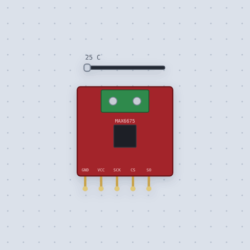
The Thermocouple converter, MAX6675 in brief
What it is, and every setting the properties panel gives it.
The MAX6675 board is the usual way to put a K-type thermocouple on an Arduino: the probe of kilns, smokers, reflow ovens and 3D printer hot ends. A thermocouple makes only tens of microvolts per degree, far below what a board’s ADC can see, so the MAX6675 amplifies it, corrects for the temperature of its own screw terminals and sends the result over a read-only SPI line as twelve bits at a quarter degree each, up to 1023 °C. On the Mokxi bench a slider sets the probe tip from 0 to 1000 °C, and a property takes the probe off the terminals. The model clocks out sixteen bits per read, flags an open thermocouple, keeps SO high impedance while CS is high and takes 0.22 s per conversion after CS rises, so a sketch that reads faster just sees the same number again, as it would with the real chip.
- Family
- Sensors
- Pins
- 5
- temperature
- 25
- probe
- true
5 pins
Named as the editor names them, so a wire lands where you expect it.
CS is high.How to read a MAX6675 thermocouple with an Arduino
Five wires: VCC to 5 V, GND to ground, and the three signal pins to any digital pins, here SCK to 6, CS to 5 and SO to 4. SO is the chip’s output, so it goes to an input, never to MOSI. The thermocouple itself screws into the board’s terminals; on the canvas it is already in place.
The library takes the three pins in the order SCK, CS, SO and does the clocking itself. Give the chip half a second after power-up to finish its first conversion, then call readCelsius() no more than about four times a second. The thermocouple project reads twice a second and prints Celsius and Fahrenheit. Drag the slider and the next line follows; untick the probe property and readCelsius() returns NAN, which the sketch reports as no thermocouple.
The chip runs from 3.0 to 5.5 V, so on an ESP32 or a Pico power it from 3.3 V and pick any three free GPIO pins.
#include <max6675.h>

MAX6675 thermocouple(6, 5, 4);   // SCK, CS, SO

void setup() {
  Serial.begin(9600);
  delay(500);                    // first conversion
}

void loop() {
  float c = thermocouple.readCelsius();
  if (isnan(c)) Serial.println("No thermocouple");
  else Serial.println(c);
  delay(500);
}
Common Thermocouple converter, MAX6675 errors and fixes
Questions and answers
What is the highest temperature the MAX6675 can read?
1023.75 °C, the top of its twelve bits at a quarter degree each. The slider on the part goes to 1000 °C.
Can the MAX6675 share SPI with other devices?
Yes. SCK and SO can be shared; each device gets its own CS, and the MAX6675 leaves SO high impedance while its CS is high.
Why does the first reading come out wrong?
The chip needs a conversion, 0.22 s, before it has anything to give. That is why the sketch waits half a second in setup().
How accurate is a MAX6675 reading?
The chip is specified to within a few degrees, and the thermocouple adds its own error. The simulation reports the slider exactly, at the chip’s quarter-degree step.
What is true about the Thermocouple converter, MAX6675, here
In its help article’s own words: what the simulation gets right, and where it stops.
Modeled
From the MAX6675 datasheet: CS low puts bit 15 on SO and each falling edge of
SCK the next bit, sixteen in all; the temperature in bits 14 to 3 at 0.25
degrees a count; bit 2 set for an open thermocouple; SO high-Z while
deselected. A conversion takes 0.22 s after CS rises, and a read before it
finishes returns the last result, so reading faster than about four times a
second repeats the same number.
Not modeled
The thermocouple's own voltage and the chip's accuracy (plus or minus 2 degrees), temperatures below 0 (the chip reads 0), and the 4.3 MHz clock limit.
From MAX6675 thermocouple converter, in full.
See the Thermocouple converter, MAX6675 in a project
One built-in project uses it. It opens in the editor, already wired.
Where it turns up in a lesson
One lesson places it in its own circuit.
The boards it is shown on
This board has a built-in project with the Thermocouple converter, MAX6675 in it.
Arduino libraries for the Thermocouple converter, MAX6675
Built in, so the sketch compiles with nothing to install. Each page has the calls, the wiring and an example to run.
The rest of the bench
Every one of these is drawn and simulated the same way.
Wire up the Thermocouple converter, MAX6675
Open the editor and push it into the breadboard. It is free, and it runs on your own machine.