Compass, HMC5883L (GY-271)
The classic GY-271 compass at 0x1E: X, Z and Y in 230 to 1370 counts a gauss, the self test and DRDY, for Adafruit_HMC5883_U.h.
- 5 pins
- 3 settings
- In 1 project
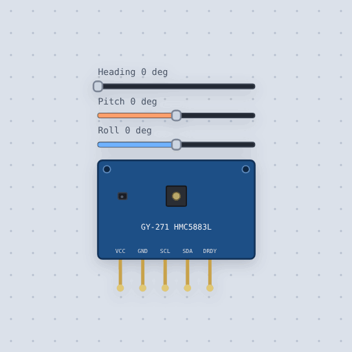
The Compass, HMC5883L (GY-271) in brief
What it is, and every setting the properties panel gives it.
The HMC5883L is Honeywell’s three-axis compass chip, read over I2C at 0x1E, on the blue GY-271 board. Flat on the bench it reads the Earth’s field, about 20 microtesla toward magnetic north and 45 down at mid-northern latitudes, and atan2 of the two horizontal readings is the heading. Configuration B sets the gain, 230 to 1370 counts a gauss, and the data comes out X, Z, Y, high byte first, from -2048 to 2047. VCC and GND take 3 V to 5 V on the board, SCL and SDA are I2C with the pull-ups on the board, and DRDY goes low for 250 microseconds when new data goes in. The part’s heading, pitch and roll are sliders. Most GY-271 boards sold today carry a QMC5883L at 0x0D instead.
- Family
- Sensors
- Pins
- 5
- pitch
- 0
- roll
- 0
- heading
- 0
5 pins
Named as the editor names them, so a wire lands where you expect it.
0x1E (0x3C to write, 0x3D to read). The board carries 4.7 k pull-ups.0x1E (0x3C to write, 0x3D to read). The board carries 4.7 k pull-ups.How to read an HMC5883L compass with an Arduino
The GY-271’s VCC goes to 5 V, GND to GND, SDA to A4 and SCL to A5, at address 0x1E. The sketch uses Adafruit’s HMC5883 Unified library: begin() puts the chip in continuous mode at 15 measurements a second, and getEvent() hands back the field in microtesla. The first sample lands two periods after begin(), so the sketch waits before its first read.
The heading is atan2 of Y over X, in degrees clockwise from magnetic north, and the sketch names the nearest of the eight points of the compass. Drag the heading slider to turn the board; tip it with pitch and roll and watch the flat-compass heading go wrong. The library divides by its own 1100 counts a gauss rather than the datasheet’s 1090, so the microtesla read about 1 percent low, as on a real board.
The board has its own 3.3 V regulator and takes 3 V to 5 V, so a 3.3 V board such as an ESP32 or a Pico drives it directly. Use that board’s I2C pins; the address is 0x1E.
Common Compass, HMC5883L (GY-271) errors and fixes
Questions and answers
What is the I2C address of the HMC5883L?
0x1E, or 0x3C to write and 0x3D to read as an 8-bit address. It cannot be changed.
What is the difference between the HMC5883L and the QMC5883L?
They do the same job on the same GY-271 board, but the QMC5883L answers at 0x0D with another register map, so each needs its own library.
How do I get a compass heading from the HMC5883L?
Take atan2 of the Y and X readings while the board is flat, turn radians into degrees and add 360 if it is negative.
What is true about the Compass, HMC5883L (GY-271), here
In its help article’s own words: what the simulation gets right, and where it stops.
Not modeled
The averaging (there is no noise to average), the high-speed I2C bit, noise, offsets, hard and soft iron, nearby magnets, and the 50 ms the chip's analog side takes to wake.
From HMC5883L compass (GY-271), in full.
See the Compass, HMC5883L (GY-271) in a project
One built-in project uses it. It opens in the editor, already wired.
The boards it is shown on
This board has a built-in project with the Compass, HMC5883L (GY-271) in it.
The rest of the bench
Every one of these is drawn and simulated the same way.
Wire up the Compass, HMC5883L (GY-271)
Open the editor and push it into the breadboard. It is free, and it runs on your own machine.