Accelerometer and compass, LSM303AGR
An accelerometer at 0x19 and a magnetometer at 0x1E in one package: a tilt-compensated compass.
- 6 pins
- 3 settings
- In 1 project
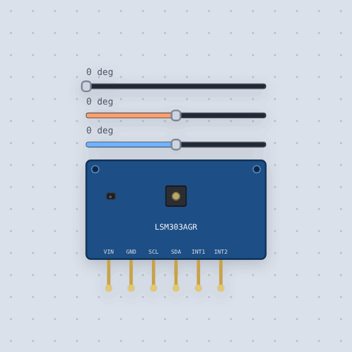
The Accelerometer and compass, LSM303AGR in brief
What it is, and every setting the properties panel gives it.
The LSM303AGR puts an accelerometer at 0x19 and a magnetometer at 0x1E in one package: the two halves of a tilt-compensated compass. The accelerometer says which way is down, the magnetometer which way is north, and together they give a heading that stays right when the board tips. VIN and GND take 3 V to 5 V on the board, SCL and SDA are I2C with both halves on the same bus and the pull-ups on the board, and INT1 and INT2 are interrupts left high-impedance by the model. The heading, pitch and roll properties are how the board sits, and the sliders turn and tip it. Aliases include the LSM303DLHC and the Adafruit LSM303AGR.
- Family
- Sensors
- Pins
- 6
- pitch
- 0
- roll
- 0
- heading
- 0
6 pins
Named as the editor names them, so a wire lands where you expect it.
How to read an LSM303AGR compass and accelerometer with an Arduino
The compass’s SDA and SCL go to the Uno’s SDA and SCL, with VIN on 5 V and GND on GND. Both halves share the bus: the accelerometer is at 0x19 and the magnetometer at 0x1E. An LTR-390 UV sensor shares the same I2C wires, on A4 and A5. The sketch includes Adafruit_LSM303_Accel and Adafruit_LTR390.
The compass heading comes from the magnetometer’s two level axes, so it is only right while the board is flat; the accelerometer says how far it is tipped. A UV index of 3 or more wants sunscreen, and the project warns there. Drag the heading slider round, tip the board with the roll slider and drag the UV slider past 3.
The board takes 3 V to 5 V, so a 3.3 V board such as an ESP32 or a Pico drives it directly. Use that board’s I2C pins.
Common Accelerometer and compass, LSM303AGR errors and fixes
Questions and answers
What are the I2C addresses of the LSM303AGR?
0x19 for the accelerometer and 0x1E for the magnetometer, on the same bus.
What is a tilt-compensated compass?
One where the accelerometer says which way is down and the magnetometer which way is north, so the heading stays right when the board tips.
Why does the heading need the board flat?
The simple heading uses only the magnetometer’s two level axes. The accelerometer says how far it is tipped, to correct for it.
What is true about the Accelerometer and compass, LSM303AGR, here
In its help article’s own words: what the simulation gets right, and where it stops.
Not modeled
The FIFO, the click and interrupt engines, the temperature sensor, hard-iron offsets, and noise.
From LSM303AGR accelerometer and compass, in full.
See the Accelerometer and compass, LSM303AGR in a project
One built-in project uses it. It opens in the editor, already wired.
The boards it is shown on
This board has a built-in project with the Accelerometer and compass, LSM303AGR in it.
The rest of the bench
Every one of these is drawn and simulated the same way.
Wire up the Accelerometer and compass, LSM303AGR
Open the editor and push it into the breadboard. It is free, and it runs on your own machine.