Magnetometer, LIS3MDL
The Earth's field on three axes, up to 6842 counts a gauss, for a compass heading.
- 6 pins
- 4 settings
- In 1 project
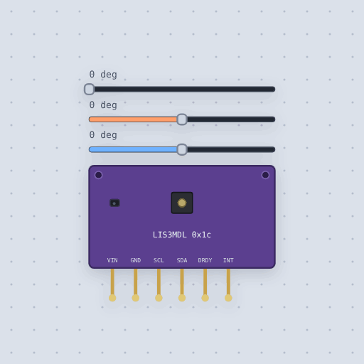
The Magnetometer, LIS3MDL in brief
What it is, and every setting the properties panel gives it.
The LIS3MDL is ST’s three-axis magnetometer, read over I2C at 0x1C, up to 6842 counts a gauss: the sensor of a digital compass. Flat on the bench it reads the Earth’s field, about 20 microtesla toward magnetic north and 45 down at mid-northern latitudes, and atan2 of the two horizontal readings is the heading. VIN and GND take 3 V to 5 V on the board, SCL and SDA are I2C with the pull-ups on the board, DRDY is low while a new sample waits and INT is the threshold interrupt, left high-impedance by the model. The part’s pitch, roll and heading are sliders, and address is 28, which is 0x1C.
- Family
- Sensors
- Pins
- 6
- address
- 28
- pitch
- 0
- roll
- 0
- heading
- 0
6 pins
Named as the editor names them, so a wire lands where you expect it.
How to read an LIS3MDL magnetometer with an Arduino
The magnetometer’s VIN goes to 5 V, GND to GND, SDA to A4 and SCL to A5, at address 0x1C. The project puts an LSM6DSOX accelerometer and gyroscope beside it on the same bus: the three sensors a drone or a head tracker needs, which way is down, how fast it turns and which way is north. Pitch comes from the accelerometer alone, and the gyroscope reads the turn rate only while the board is moving.
The heading comes from atan2 of the two horizontal field readings. Drag the heading slider on the LIS3MDL, and the pitch and heading sliders on the LSM6DSOX to see the gyro move. The sketch uses the Adafruit LSM6DSOX and LIS3MDL libraries.
The board takes 3 V to 5 V, so a 3.3 V board such as an ESP32 or a Pico drives it directly. Use that board’s I2C pins; the address is 0x1C.
Common Magnetometer, LIS3MDL errors and fixes
Questions and answers
What is the I2C address of the LIS3MDL?
0x1C.
How do I get a compass heading from a magnetometer?
Take atan2 of the two horizontal readings while the board is flat. Flat on the bench it reads about 20 microtesla toward magnetic north.
How sensitive is the LIS3MDL?
Up to 6842 counts a gauss.
What is true about the Magnetometer, LIS3MDL, here
In its help article’s own words: what the simulation gets right, and where it stops.
Not modeled
The interrupt threshold, the self-test, offsets, noise, and nearby magnets.
From LIS3MDL magnetometer, in full.
See the Magnetometer, LIS3MDL in a project
One built-in project uses it. It opens in the editor, already wired.
The boards it is shown on
This board has a built-in project with the Magnetometer, LIS3MDL in it.
The rest of the bench
Every one of these is drawn and simulated the same way.
Wire up the Magnetometer, LIS3MDL
Open the editor and push it into the breadboard. It is free, and it runs on your own machine.