Water flow sensor, YF-S201
A pinwheel and a Hall sensor in a pipe: SIG pulses 7.5 times a second per liter a minute. Also the YF-S401, YF-B10 and YF-DN50.
- 3 pins
- 2 settings
- In 2 projects
- In 1 lesson
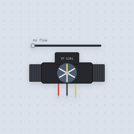
The Water flow sensor, YF-S201 in brief
What it is, and every setting the properties panel gives it.
The YF-S201 is a Hall effect water flow sensor: a pinwheel in a pipe pulses SIG as the water turns it, 7.5 pulses a second for every liter a minute, which is 450 pulses a liter. The pins are VCC, 5 V to 18 V, GND and SIG. The model property also offers the YF-S401, the brass YF-B10 and the YF-DN50, each with its own formula, and the flow property is the flow it starts with in liters a minute. SIG is high over 4.5 V and low under 0.5 V on 5 V, 50 percent duty, an open collector with a 10 k pull-up to VCC inside. The slider in the window sets the flow and the wheel turns with it. Real accuracy of 3 to 10 percent is not modeled.
- Family
- Sensors
- Pins
- 3
- model
- YF-S201 (or YF-S401, YF-B10, YF-DN50)
- flow
- 0
3 pins
Named as the editor names them, so a wire lands where you expect it.
How to read a YF-S201 water flow sensor with an Arduino
VCC goes to the Uno’s 5 V, GND to ground and SIG to pin 2, which is an interrupt pin. The sensor makes 7.5 pulses a second for each liter a minute, so a sketch counts the pulses on an interrupt and divides. Do not count them in loop() with digitalRead(): at 30 L/min the sensor makes 225 pulses a second.
This sketch counts falling edges, and once a second turns the new pulses into the flow, pulses a second times 2/15 in L/min, and the total, 450 pulses to the liter. A 16x2 LCD on its I2C backpack, SDA on A4 and SCL on A5, shows both. Drag the flow slider and the wheel and the numbers follow.
The pull-up inside goes to VCC, so SIG swings to whatever you power the sensor from. From 12 V it puts 12 V pulses on a board pin, so run it from 5 V.
const int SENSOR = 2;
volatile unsigned long pulses = 0;
unsigned long counted = 0;
unsigned long lastSecond = 0;

void onPulse() {
  pulses++;
}

void setup() {
  Serial.begin(115200);
  pinMode(SENSOR, INPUT_PULLUP);
  attachInterrupt(digitalPinToInterrupt(SENSOR), onPulse, FALLING);
  lastSecond = millis();
}

void loop() {
  if (millis() - lastSecond < 1000) return;
  lastSecond += 1000;
  noInterrupts();
  unsigned long all = pulses;
  interrupts();
  unsigned long thisSecond = all - counted;
  counted = all;
  unsigned long tenths = thisSecond * 4 / 3;   // tenths of a liter a minute
  unsigned long ml = all * 20 / 9;             // 450 pulses a liter
  Serial.print("flow ");
  Serial.print(tenths / 10);
  Serial.print('.');
  Serial.print(tenths % 10);
  Serial.print(" L/min, total ");
  Serial.print(ml);
  Serial.println(" ml");
}
Common Water flow sensor, YF-S201 errors and fixes
Questions and answers
How many pulses a liter does the YF-S201 make?
450, since the frequency in hertz is 7.5 times the flow in liters a minute.
What flow range does the YF-S201 measure?
1 to 30 liters a minute.
Which Arduino pin should the flow sensor use?
An interrupt pin, 2 or 3 on an Uno, so each pulse is counted with attachInterrupt().
What is true about the Water flow sensor, YF-S201, here
In its help article’s own words: what the simulation gets right, and where it stops.
Modeled
From the spec sheets and listings, which are all the paperwork there is:
| Model | Pipe | Formula (F in Hz, Q in L/min) | Pulses a liter | Range |
|---|---|---|---|---|
| YF-S201 | G1/2 | F = 7.5 x Q |
450 | 1 to 30 L/min |
| YF-S401 | 1/8 inch | F = 98 x Q |
5880 | 0.3 to 6 L/min |
| YF-B10 | G1, brass | F = 8 x Q - 4 |
about 476 | 2 to 50 L/min |
| YF-DN50 | G2 | F = 0.2 x Q |
12 | 10 to 200 L/min |
The YF-S401's figures are DFRobot's (SEN0216). The YF-B10's are the SEA listing's
and most sellers'; an older one-page sheet gives 6 x Q - 8, so calibrate a real
one. Under 0.5 L/min its formula gives no pulses, and neither does the model.
The output. High over 4.5 V and low under 0.5 V on 5 V, 50% duty: an open
collector with a pull-up inside, here 10 kohm to VCC (an assumption). A sketch's own
INPUT_PULLUP changes nothing.
Not modeled
A real sensor's accuracy, 3 to 10% (the model's pulses are exact, so calibrate a real one with a measuring jug); the low flow at which a real wheel stops turning; the water pressure; and a wheel that spins on for a moment after the tap closes.
From Water flow sensor, YF-S201, in full.
See the Water flow sensor, YF-S201 in a project
2 built-in projects use it. Each opens in the editor, already wired.
Where it turns up in a lesson
One lesson places it in its own circuit.
The boards it is shown on
This board has a built-in project with the Water flow sensor, YF-S201 in it.
The rest of the bench
Every one of these is drawn and simulated the same way.
Wire up the Water flow sensor, YF-S201
Open the editor and push it into the breadboard. It is free, and it runs on your own machine.