TL431 shunt reference
A Zener you set with two resistors: it sinks what it takes to hold REF at 2.495 V, so Vka = 2.495 V x (1 + R1/R2).
- 3 pins
- In 1 project
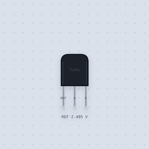
The TL431 shunt reference in brief
What it is, and where it sits on the bench.
The TL431 is a three-legged chip that behaves like a Zener diode you can set. Between its cathode K and anode A it sinks whatever current it takes to hold its REF leg 2.495 V above the anode, and no more. Tie REF to K and it is a 2.495 V Zener with a fifth of an ohm of dynamic impedance, far stiffer than a real Zener. Put two resistors across it, R1 from K to REF and R2 from REF to A, and the cathode settles at 2.495 V times one plus R1 over R2, plus the 2 microamps REF draws times R1. The Mokxi part follows TI’s typical figures: the 2.495 V reference at 10 mA, the 1.4 mV per volt the reference loses as the cathode rises, 0.2 ohm of dynamic impedance, the 0.4 mA it needs to regulate at all, and a low of about 2 V when it is used open loop as a comparator. The spread between parts, temperature drift and the capacitor values that make a real one oscillate are not modeled.
- Family
- Power and wiring
- Pins
- 3
3 pins
Named as the editor names them, so a wire lands where you expect it.
How to set a voltage with a TL431 shunt reference
The built-in project feeds 12 V through a 680 ohm resistor into the TL431’s cathode, with the anode on ground. Two 10 k resistors make a divider from the cathode to ground, and their middle goes to REF. A meter on the cathode reads 5.00 V, and the readout under the part shows the current through it, about 10 mA.
The formula is Vka = 2.495 V x (1 + R1 / R2) + Iref x R1. With two 10 k resistors that is 4.99 V plus 2 uA times 10 k, 5.01 V. The meter reads a little less because the reference sags 1.4 mV for every volt on the cathode, which the divider doubles. Make R2 4.7 k and the output goes to about 7.8 V; take the divider out and tie REF to K, and it is a 2.495 V Zener.
Like a Zener it only sinks current, so it always needs a feed resistor from a higher supply. Size it so the TL431 gets at least 1 mA after the load takes its share: (12 - 5) / 680 is 10.3 mA here. A 47 k feed resistor gives 0.15 mA, under the minimum, and the output sags below 5 V. With no feedback at all, REF above 2.495 V pulls the cathode down to about 2 V, a handy comparator for 5 V logic.
There is no board in this circuit. To give an Arduino’s ADC an accurate 2.5 V reference, tie REF to K, feed it from 5 V through 1 k and connect K to AREF.
Common TL431 shunt reference errors and fixes
Questions and answers
What is the TL431 output voltage formula?
Vka = 2.495 V x (1 + R1 / R2) + Iref x R1, where R1 runs from the cathode to REF and R2 from REF to the anode. Two 10 k resistors give about 5.0 V.
What is the TL431 pinout?
In the TO-92, flat face toward you and legs down, the legs are REF, anode and cathode from the left. TI numbers them 3 REF, 2 ANODE, 1 CATHODE.
How much current does a TL431 need?
At least 1 mA to be sure of regulating; TI gives 0.4 mA typical and 1 mA maximum for the minimum, and 100 mA as the most it should carry.
Can a TL431 be used as a comparator?
Yes. With REF on a divider and a pull-up on the cathode, the cathode goes low when REF passes 2.495 V, but only to about 2 V. That reads as low on 5 V logic, not on 3.3 V.
What is true about the TL431 shunt reference, here
In its help article’s own words: what the simulation gets right, and where it stops.
Modeled
The figures are the typical ones from TI's TL431 sheet (SLVS543S, May 2024), at 25 C.
The reference, 2.495 V at the sheet's test point: REF on K, 10 mA.
The second term. 2 uA flow into REF, so a 10 k R1 adds 20 mV. (The sheet's
section 9.2.2.2.1 prints that term with a minus sign; its Figure 7-2 and the physics
have it as a plus, and so does the model.)
The cathode's pull on the reference. The reference drops 1.4 mV for every volt on the cathode up to 10 V, and 1 mV a volt from 10 V to 36 V. At 5 V that is 3.5 mV, and the 5 V divider doubles it.
Dynamic impedance, 0.2 ohm from 1 mA to 100 mA, so the cathode moves 9 mV
between 5 mA and 50 mA. With a divider it is multiplied by 1 + R1/R2, as the sheet
says, because the divider is part of the circuit.
The minimum current. The amplifier needs 0.4 mA of its own (the sheet allows up to 1 mA). Feed it less and the cathode sags under its set voltage.
As a comparator. With no feedback, REF above 2.495 V pulls the cathode down,
but only to about 2 V: the output is a Darlington's collector. That is enough for 5 V
logic and not for 3.3 V, as the sheet warns. Below 2.495 V it lets go and leaks
0.1 uA.
Backwards, the substrate diode from A to K conducts, about 0.75 V at 10 mA.
That figure is assumed: the sheet gives none.
Not modeled
The spread between parts: a real TL431 can sit anywhere from 2.440 V to 2.550 V, the A grade within 1 % and the B grade within 0.5 %, and the model is always the typical 2.495 V. Drift with temperature. The capacitor values that make a real one oscillate (the sheet's stability chart): the model is stable with any capacitor. Its response time and gain roll-off. Damage from more than 100 mA or 37 V.
From TL431 shunt reference, in full.
See the TL431 shunt reference in a project
One built-in project uses it. It opens in the editor, already wired.
The rest of the bench
Every one of these is drawn and simulated the same way.
Wire up the TL431 shunt reference
Open the editor and push it into the breadboard. It is free, and it runs on your own machine.