RF transmitter, FS1000A
DATA high is the 433 MHz carrier on: rc-switch or RH_ASK sends, and every receiver on the canvas hears it.
- 4 pins
- In 1 project
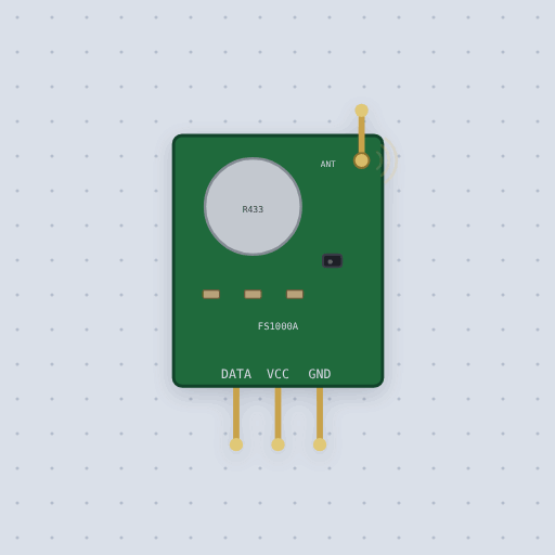
The RF transmitter, FS1000A in brief
What it is, and where it sits on the bench.
The FS1000A is the 433 MHz transmitter half of the pair in nearly every Arduino kit: a SAW resonator and one transistor, with no chip, so DATA high switches the carrier on and DATA low switches it off. Its pins are DATA, VCC and GND along the bottom, on 3 to 12 V, plus an ANT pad for a 17 cm wire. A 3.3 V or 5 V board pin keys it, and a library makes every pulse: rc-switch sends remote-socket codes with send(5393, 24), RadioHead’s RH_ASK sends checked messages from pin 12. In Mokxi the ANT pad of every 433 MHz module joins one shared air, so each XY-MK-5V receiver on the canvas hears every transmitter with no wire, and two sending at once spoil each other’s codes. Distance, walls and the antenna are not modeled.
- Family
- Clocks and links
- Pins
- 4
4 pins
Named as the editor names them, so a wire lands where you expect it.
How to use the FS1000A 433 MHz transmitter with an Arduino
Wire VCC to 5 V, GND to GND and DATA to any digital pin, and leave the antenna pad alone. The module has no chip: DATA high switches the 433 MHz carrier on and low switches it off, so a library makes every pulse of a code for you.
With rc-switch, call enableTransmit(10) once in setup() and send(code, 24) to send a 24-bit code, the kind remote sockets and doorbells use; send() repeats it so a receiver can check it. Every receiver on the canvas hears every transmitter, with no wire between them, so the receiving board is wired only to its own XY-MK-5V.
The same code runs on an ESP32 or a Pico; a 3.3 V pin drives DATA. On a real one, more volts on VCC (up to 12 V) and a 17 cm wire on the antenna pad give more range.
RCSwitch mySwitch = RCSwitch();
mySwitch.enableTransmit(10);
mySwitch.send(5393, 24);What is true about the RF transmitter, FS1000A, here
In its help article’s own words: what the simulation gets right, and where it stops.
Not modeled
Distance, walls and the antenna: every receiver on the canvas hears every transmitter at full strength. That is right for a desk; the real pair reaches about 20 to 100 m in the open with a 17 cm wire on ANT. The 315 MHz version is the same part on another frequency, and here all modules share one. The carrier switches at once, where a real one takes some tens of microseconds, and the supply current (about 10 to 40 mA while sending) is not drawn.
From 433 MHz transmitter, FS1000A, in full.
See the RF transmitter, FS1000A in a project
One built-in project uses it. It opens in the editor, already wired.
The boards it is shown on
This board has a built-in project with the RF transmitter, FS1000A in it.
The rest of the bench
Every one of these is drawn and simulated the same way.
Wire up the RF transmitter, FS1000A
Open the editor and push it into the breadboard. It is free, and it runs on your own machine.