Phototransistor
The Arduino Starter Kit light sensor: a collector current that follows the light, read across a resistor. Drag the slider.
- 2 pins
- 1 setting
- In 1 project
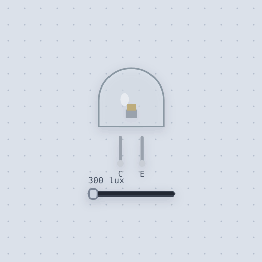
The Phototransistor in brief
What it is, and every setting the properties panel gives it.
The phototransistor is a two lead NPN in a clear 5 mm package, the light sensor in the Arduino Starter Kit, which carries six of them for the Color Mixing Lamp and the Light Theremin. There is no base lead: light through the lens makes a photocurrent where the base would be, and the transistor’s gain turns it into a collector current several hundred times larger. The pins are C, the collector, to the supply side, and E, the emitter, to the ground side, usually through the resistor you read across. The sensitivity property is the collector current per lux in microamps with 5 V across the part, 2 by default. A slider is the light in lux, 0 to 5000.
- Family
- Sensors
- Pins
- 2
- sensitivity
- 2
2 pins
Named as the editor names them, so a wire lands where you expect it.
How to read a phototransistor with an Arduino and play a theremin
The Starter Kit wiring: the collector C to 5 V, the emitter E to analog pin A0, and a 10 k resistor from that pin to ground. The pin reads the collector current times 10 k, so it is 0 in the dark and near 1023 in a lit room. A piezo on pin 8 has its other leg on ground.
The sketch maps the reading from 0 to 1023 onto 120 to 1500 Hz and plays it with tone(), so the pitch follows the light. Drag the light slider in the part’s window, 0 to 5000 lux, and listen. A phototransistor is a current that follows the light, so across 10 k it reads in proportion until the resistor runs out of voltage and it saturates a little short of 5 V.
const int SENSOR_PIN = A0;
const int PIEZO_PIN = 8;
const int LOW_PITCH = 120;    // hertz, in the dark
const int HIGH_PITCH = 1500;  // hertz, at full scale

void setup() {
  Serial.begin(9600);
}

void loop() {
  int light = analogRead(SENSOR_PIN);
  int pitch = map(light, 0, 1023, LOW_PITCH, HIGH_PITCH);
  tone(PIEZO_PIN, pitch);
  Serial.print("light ");
  Serial.print(light);
  Serial.print(" -> ");
  Serial.print(pitch);
  Serial.println(" Hz");
  delay(10);
}
Common Phototransistor errors and fixes
Questions and answers
What are the phototransistor’s pins?
C, the collector, to the supply side, and E, the emitter, to the ground side. There is no base lead.
What is the difference between a phototransistor and an LDR?
An LDR is a resistor whose value follows the light. A phototransistor is a current that follows the light, a collector current several hundred times the photocurrent.
What is the sensitivity of the model?
2 microamps of collector current per lux with 5 V across the part, set by the sensitivity property.
What is true about the Phototransistor, here
In its help article’s own words: what the simulation gets right, and where it stops.
Modeled
A current, not a resistance. In the active region the collector current is
sensitivity x lux, nearly independent of the voltage across the part: 20 lux
is 40 uA, which is 0.4 V across 10 k.
Saturation. It is Ebers-Moll with the base current set by the light, so as the resistor's drop leaves less than a few tenths of a volt across the part the current falls off, and the reading stops near 4.8 V rather than reaching 5 V.
Dark current. 10 nA in the dark, a tenth of a millivolt on 10 k.
Backwards it barely works. Reversed, it runs on the reverse gain, a hundredth of the forward one, so a phototransistor put in the wrong way around reads almost nothing.
The Early effect. The current climbs a little with the voltage across the part, about a tenth from 0 to 5 V, as on a curve tracer.
The numbers are assumptions in the range the visible-light phototransistors' sheets print: tens of microamps at 20 lux, a dark current of tens of nanoamps at most, a gain of several hundred. Real parts vary by a factor of two or more from one to the next.
Not modeled
Color: a real one also sees infrared, and its response peaks in the near infrared, so a filament lamp reads brighter than its lux and an LED dimmer. The angle of the light, the 10 to 20 microsecond rise and fall time, and temperature.
From Phototransistor, in full.
See the Phototransistor in a project
One built-in project uses it. It opens in the editor, already wired.
The boards it is shown on
This board has a built-in project with the Phototransistor in it.
The rest of the bench
Every one of these is drawn and simulated the same way.
Wire up the Phototransistor
Open the editor and push it into the breadboard. It is free, and it runs on your own machine.