Photoresistor sensor module
The LDR on a board with a comparator: an analog level, and a digital output set by its trimmer.
- 4 pins
- 4 settings
- In 9 projects
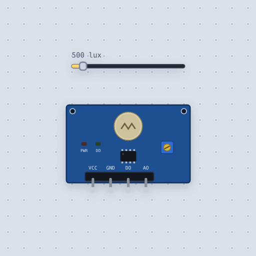
The Photoresistor sensor module in brief
What it is, and every setting the properties panel gives it.
The photoresistor sensor module puts a light-dependent resistor on the same four-pin LM393 comparator board as the flame sensor, with pins VCC, GND, DO and AO and a supply of 3.3 to 5 volts, so it wires straight to an Uno or an ESP32. The board hangs a 10 kilohm resistor from VCC to AO and the cell from AO to ground, which means AO falls as the light rises, the reverse of what most people expect. DO is the comparator’s open-collector output with its own 10 kilohm pull-up: high in the dark and low in the light, with the DO lamp lit while it is low. Mokxi’s cell is 50 kilohms at 10 lux with a gamma of 0.7, both properties, so AO crosses half the supply near 100 lux, right where the default threshold of 0.5 sits. The slider sets the light in lux, and AO is driven with the divider’s own source resistance. Reading DO with analogRead gives only 0 or the supply. The cell’s response time and the chatter a real board shows right at the threshold are not modeled.
- Family
- Sensors
- Pins
- 4
- threshold
- 0.5
- rl10
- 50
- gamma
- 0.7
- lux
- 500
4 pins
Named as the editor names them, so a wire lands where you expect it.
How to use a photoresistor module with an Arduino
Wire VCC to 5 V, GND to GND, DO to pin 2 and AO to A0. Use DO when you want a switch: digitalRead() gives HIGH in the dark and LOW in the light, and the blue trimmer sets where it changes, about 100 lux out of the bag. Use AO when you want a number, remembering that it reads lower as the light gets brighter.
The dusk switch does both: it turns the lamp on pin 13 on when DO goes high and prints the AO reading twice a second, so you can see which number the trimmer is set to. Turn the trimmer, not the code, to move the switching point.
Powered from 3.3 V on an ESP32 or a Pico, AO swings across that supply instead, and the threshold is still the same fraction of it.
void setup() {
  Serial.begin(9600);
  pinMode(2, INPUT);
  pinMode(LED_BUILTIN, OUTPUT);
}
void loop() {
  bool dark = digitalRead(2) == HIGH;
  digitalWrite(LED_BUILTIN, dark ? HIGH : LOW);
  Serial.println(analogRead(A0));  // lower is brighter
  delay(500);
}What is true about the Photoresistor sensor module, here
In its help article’s own words: what the simulation gets right, and where it stops.
Modeled
The divider. 10 k from VCC to AO and the cell from AO to ground, so AO
is the supply times R / (R + 10 k), and it drives that voltage with the divider's
own source resistance.
The cell's curve, R = rl10 x (10 / lux) ^ gamma, a megohm in the dark: 50 k at
10 lux, about 10 k at 100 lux, where AO crosses half the supply.
The comparator. The LM393 compares AO with the trimmer and pulls DO low
through its open collector while AO is below it; high is the board's 10 k
pull-up. That is the same board the flame and rain sensors
stand on.
Not modeled
The cell's response time and light history, the LM393's lack of hysteresis (a real board chatters with the light right at the threshold), and color: lux here is the eye's lux.
From Photoresistor sensor module, in full.
See the Photoresistor sensor module in a project
9 built-in projects use it. Each opens in the editor, already wired.
The boards it is shown on
Each of these 2 boards has a built-in project with the Photoresistor sensor module in it.
The rest of the bench
Every one of these is drawn and simulated the same way.
Wire up the Photoresistor sensor module
Open the editor and push it into the breadboard. It is free, and it runs on your own machine.