NTC temperature sensor module
A 10 k thermistor in a divider on a little board: an analog voltage that falls as it warms.
- 3 pins
- 2 settings
- In 1 project
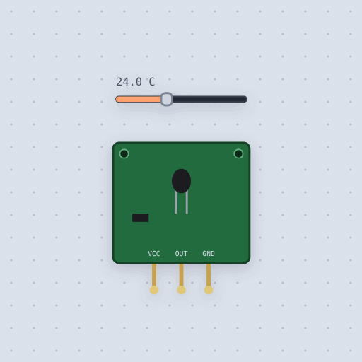
The NTC temperature sensor module in brief
What it is, and every setting the properties panel gives it.
The NTC module is a 10 k thermistor bead and a 10 k resistor on a three-pin board, sold as the KY-013. On an Uno, VCC goes to 5 V, GND to ground and OUT to A0; on an ESP32, power it from 3.3 V, read OUT on an ADC1 pin such as GPIO 34, and change the sketch’s 1023 to 4095. In Mokxi the 10 k runs from VCC to OUT and the thermistor from OUT to ground, so OUT is half the supply at 25 °C and falls as the bead warms. The bead follows the beta equation, R = 10 k x exp(B (1/T - 1/298.15)), with beta 3950 by default; the slider runs from -40 to 125 °C and starts at 24, and the usual tutorial formula gives it back to a few hundredths of a degree. A load on OUT pulls it, as on a real divider. The classic mistake is a BETA in the sketch that differs from the bead’s: right at 25 °C and drifting further off either side. Self-heating, thermal lag and the few percent tolerance of a real bead and resistor are not modeled.
- Family
- Sensors
- Pins
- 3
- temperature
- 24
- beta
- 3950
3 pins
Named as the editor names them, so a wire lands where you expect it.
How to use the KY-013 thermistor module with an Arduino
The module is a 10 k thermistor under a 10 k resistor, so it needs only three wires: VCC to 5 V, GND to GND and OUT to A0. In the kit circuit here it sits below the Uno and takes its supply straight from the power header.
OUT is half the supply at 25 °C and falls as the bead warms. The sketch turns the reading back into the thermistor’s resistance, 10000.0 * reading / (1023.0 - reading), and the beta equation turns that into degrees, twice a second. Drag the module’s temperature and watch the serial monitor follow it.
The beta in the sketch must match the bead’s, 3950 here. With the wrong one the reading is still right at 25 °C and drifts further off the further you go either side, which is easy to miss on a desk at room temperature.
On an ESP32, power it from 3.3 V and read OUT on an ADC1 pin such as GPIO 34; the divider still sits at half the supply at 25 °C, but the full scale is 4095, so change both 1023s.
void setup() {
  Serial.begin(9600);
}
void loop() {
  int reading = analogRead(A0);
  float r = 10000.0 * reading / (1023.0 - reading);
  float kelvin = 1.0 / (log(r / 10000.0) / 3950.0 + 1.0 / (25.0 + 273.15));
  Serial.print(kelvin - 273.15);
  Serial.println(" C");
  delay(500);
}What is true about the NTC temperature sensor module, here
In its help article’s own words: what the simulation gets right, and where it stops.
Modeled
The divider: 10 k from VCC to OUT, the thermistor from OUT to ground, so
OUT falls as the bead warms and its resistance falls. It is driven as the divider
it is, the two resistances in parallel behind its voltage, so a load on OUT pulls
it.
The beta model, R = 10 k x exp(B (1/T - 1/298.15)), the same as the bare
thermistor: the tutorial's
formula gives the slider's temperature back to a few hundredths of a degree.
Not modeled
Self-heating, the bead's thermal lag (it follows the slider at once), and the tolerance of a real bead and resistor, a few percent each, which on a real module is a degree or two of error.
From NTC temperature sensor module, in full.
See the NTC temperature sensor module in a project
One built-in project uses it. It opens in the editor, already wired.
The boards it is shown on
This board has a built-in project with the NTC temperature sensor module in it.
The rest of the bench
Every one of these is drawn and simulated the same way.
Wire up the NTC temperature sensor module
Open the editor and push it into the breadboard. It is free, and it runs on your own machine.