Accelerometer, ADXL345
Three axes of acceleration on I2C at 0x53, 2 to 16 g, from the GY-291 board. Drag it to tip it.
- 8 pins
- In 1 project
- In 1 lesson
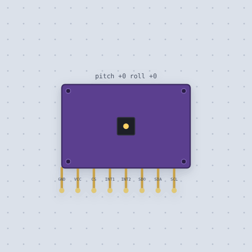
The Accelerometer, ADXL345 in brief
What it is, and where it sits on the bench.
The ADXL345 is Analog Devices’ three-axis accelerometer, sold on the GY-291 board with eight pins: GND, VCC, CS, INT1, INT2, SDO, SDA and SCL. It takes 3.3 or 5 V. CS is pulled high for I2C and should be left alone; SDO low or open puts it at 0x53, high at 0x1D. On an Uno SDA and SCL go to A4 and A5, on an ESP32 to GPIO 21 and 22. Mokxi models the datasheet over I2C: DEVID 0xE5, standby at power-on with the data registers at zero until bit 3 of POWER_CTL is set, 256 counts a g on the 2 g range in 10-bit mode or 3.9 mg a count at full resolution, saturation past the range, new samples at the BW_RATE rate, 100 Hz at reset, DATA_READY on INT1 or INT2, and the offset registers at 15.6 mg a count. You drag the board to tip it, and gravity is resolved onto the axes, so flat is 1 g on Z. The classic mistake is reading zeros from a chip never put in measure mode. SPI, the tap and free-fall detectors, the FIFO, self-test and noise are not modeled.
- Family
- Sensors
- Pins
- 8
8 pins
Named as the editor names them, so a wire lands where you expect it.
How to use the ADXL345 accelerometer with an Arduino
VCC to 5 V, GND to GND, SDA to A4 and SCL to A5. Leave CS, SDO, INT1 and INT2 as the GY-291 board pulls them: CS high selects I2C, and SDO low or open puts the chip at 0x53, the address the Adafruit library expects.
The chip starts in standby and reads zeros until it is told to measure, which accel.begin() does. setRange(ADXL345_RANGE_16_G) picks the range, and getEvent() fills a sensors_event_t with the three axes in m/s^2; getX(), getY() and getZ() give raw counts, 3.9 mg each at full resolution. The tilt level calls it level when X and Y are both under about 13 counts. Drag the board in the circuit to tip it.
On an ESP32, power the GY-291 from 3.3 V and use GPIO 21 for SDA and 22 for SCL; with SDO tied high the address is 0x1D instead.
#include <Wire.h>
#include <Adafruit_Sensor.h>
#include <Adafruit_ADXL345_U.h>
Adafruit_ADXL345_Unified accel = Adafruit_ADXL345_Unified(12345);
void setup() {
  Serial.begin(9600);
  if (!accel.begin()) while (1) delay(10);
  accel.setRange(ADXL345_RANGE_16_G);
}
void loop() {
  sensors_event_t event;
  accel.getEvent(&event);
  Serial.print(event.acceleration.x);
  Serial.print(' ');
  Serial.print(event.acceleration.y);
  Serial.print(' ');
  Serial.println(event.acceleration.z);
  delay(300);
}What is true about the Accelerometer, ADXL345, here
In its help article’s own words: what the simulation gets right, and where it stops.
Modeled
From the ADXL345 datasheet, over I2C:
Standby at power-on. The chip does not measure until bit 3 of POWER_CTL
(0x2D) is set; until then the data registers read zero. DEVID (0x00) reads 0xE5.
The scale. In 10-bit mode 256, 128, 64 or 32 counts a g on the 2, 4, 8 and 16 g ranges; at full resolution 3.9 mg a count on every range. Past the range the reading saturates.
The data rate. A new sample lands at the BW_RATE rate, 100 Hz at reset, and
sets DATA_READY, which reading the data clears and which drives INT1 or INT2
when enabled.
Offsets in OFSX, OFSY and OFSZ add to the output at 15.6 mg a count, and
left justification and the interrupt polarity follow DATA_FORMAT.
Gravity. The tilt is resolved onto the axes as on the MPU6050: flat is 1 g on Z, tipped 30 degrees nose up is -0.5 g on X.
Not modeled
SPI (with CS held low the chip ignores I2C, and SPI itself is not modeled), the
tap, double-tap, activity and free-fall detectors (their registers hold what is
written, and no event fires), the FIFO (it reads as bypass), self-test, noise and
the offset and sensitivity errors the sheet allows.
From ADXL345 accelerometer, in full.
See the Accelerometer, ADXL345 in a project
One built-in project uses it. It opens in the editor, already wired.
Where it turns up in a lesson
One lesson places it in its own circuit.
The boards it is shown on
This board has a built-in project with the Accelerometer, ADXL345 in it.
Arduino libraries for the Accelerometer, ADXL345
Built in, so the sketch compiles with nothing to install. Each page has the calls, the wiring and an example to run.
The rest of the bench
Every one of these is drawn and simulated the same way.
Wire up the Accelerometer, ADXL345
Open the editor and push it into the breadboard. It is free, and it runs on your own machine.