Three-channel current monitor, INA3221
Three shunts, three bus voltages, one I2C address: each rail of a project measured at once.
- 10 pins
- 1 setting
- In 2 projects
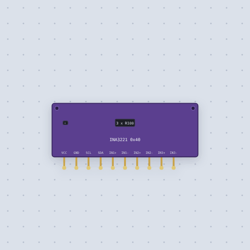
The Three-channel current monitor, INA3221 in brief
What it is, and every setting the properties panel gives it.
The INA3221 is a three-channel current monitor from TI. It measures three shunts and three bus voltages at one I2C address. That makes it a good fit for a project with several supply rails. Each channel is a 0.1 ohm shunt in series with its load. The bus voltage is read at the shunt's load end. In Mokxi you can wire its SDA and SCL lines to an Arduino, put a load in series with a channel's shunt pins, and read current and voltage in a sketch. The simulator reports each channel's current through its shunt in amps while the project runs. The editor has one setting, the I2C address, which starts at 64. The model does not include the critical and warning alerts or the power-valid window. Adafruit's library, shipped as Adafruit_INA3221.h, works here with channels 0 to 2.
- Family
- Sensors
- Pins
- 10
- address
- 64
10 pins
Named as the editor names them, so a wire lands where you expect it.
How to use the INA3221 current monitor with an Arduino
The example project is called "Two rails". It is built in and opens in the editor as drawn. An INA226 watches a 12 V rail and an INA3221 watches a 5 V one. Each rail's voltage and current, and the power, all ride on one I2C bus.
The wiring is short. The INA3221's VCC goes to the Arduino's 5V, GND to GND, SDA to A4 and SCL to A5. IN1+ connects to 5 V and IN1- to pin 1 of a filament lamp, so the lamp's current flows through the channel 1 shunt.
With default settings the serial monitor printed: "12V rail 12.00 V 109 mA 1313 mW 5V rail 4.99 V 57 mA" and then "12V rail 12.00 V 100 mA 1200 mW 5V rail 4.99 V 54 mA". The two lines differ because a filament lamp's resistance rises as its filament warms up, so the current it draws drops a little.
Things to try: swap a lamp for another model and watch its current follow.
// Two rails: an INA226 watches a 12 V rail and an INA3221 a 5 V one, each
// with its own load, both on the I2C bus, the way a bench supply or a robot's
// power board keeps an eye on what everything draws.
//
//   INA226 (0x40)    SDA -> SDA   SCL -> SCL   on the 12 V rail's load
//   INA3221 (0x41)   SDA -> A4    SCL -> A5    channel 1 on the 5 V load
//
// Each module carries a 0.1 ohm shunt in series with its load, and reads the
// small voltage across it: the current. The INA226 reads the rail's own
// voltage on VBUS too, and works out the power.
//
// Things to try. Swap a lamp for another model and watch its current follow.

#include <Wire.h>
#include "INA226.h"
#include "Adafruit_INA3221.h"

INA226 rail12(0x40);
Adafruit_INA3221 rail5;

void setup() {
  Serial.begin(9600);
  Wire.begin();
  rail12.begin();
  rail12.setMaxCurrentShunt(0.8, 0.1);
  rail5.begin(0x41, &Wire);
  rail5.setShuntResistance(0, 0.1);
  Serial.println("Two rails");
}

void loop() {
  delay(50);
  Serial.print("12V rail ");
  Serial.print(rail12.getBusVoltage(), 2);
  Serial.print(" V ");
  Serial.print(rail12.getCurrent_mA(), 0);
  Serial.print(" mA ");
  Serial.print(rail12.getPower_mW(), 0);
  Serial.print(" mW   5V rail ");
  Serial.print(rail5.getBusVoltage(0), 2);
  Serial.print(" V ");
  Serial.print(rail5.getCurrentAmps(0) * 1000, 0);
  Serial.println(" mA");
  delay(450);
}
Common Three-channel current monitor, INA3221 errors and fixes
Questions and answers
How many currents can an INA3221 measure?
Three. Each channel is a 0.1 ohm shunt in series with its load, and it also reads the bus voltage at the shunt's load end.
What voltage can the INA3221 run on?
From 2.7 to 5.5 V on VCC. In the example it runs from the Arduino's 5V pin.
What I2C address does the INA3221 use?
The address range is 0x40 to 0x43. In Mokxi the editor setting starts at 64, which is 0x40.
Which Arduino library works with the INA3221 in Mokxi?
Adafruit's library, shipped as Adafruit_INA3221.h. Use channels 0 to 2 and set each shunt resistance to 0.1 ohm.
What is true about the Three-channel current monitor, INA3221, here
In its help article’s own words: what the simulation gets right, and where it stops.
Not modeled
The critical and warning alerts and their pins, and the power-valid window.
From INA3221 three-channel current monitor, in full.
See the Three-channel current monitor, INA3221 in a project
2 built-in projects use it. Each opens in the editor, already wired.
The boards it is shown on
This board has a built-in project with the Three-channel current monitor, INA3221 in it.
The rest of the bench
Every one of these is drawn and simulated the same way.
Wire up the Three-channel current monitor, INA3221
Open the editor and push it into the breadboard. It is free, and it runs on your own machine.