Power monitor, INA226
Current, bus voltage and power through a real 0.1 ohm shunt, 2.5 uV a count, over I2C.
- 8 pins
- 1 setting
- In 1 project
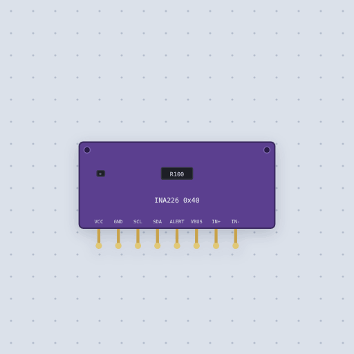
The Power monitor, INA226 in brief
What it is, and every setting the properties panel gives it.
The INA226 is TI’s current and power monitor, the more precise sibling of the INA219. It measures the voltage across a shunt resistor to 2.5 microvolts, the bus voltage on a pin of its own and the power, and reports them over I2C. On the common CJMCU-226 board the shunt is a real 0.1 ohm resistor between IN+ and IN-, in series with the load, and VBUS is tied to the load’s supply side. Mokxi models the sixteen-bit registers: the configuration, the shunt at 2.5 microvolts a count, the bus at 1.25 millivolts, power, current, the calibration, the mask and enable with its conversion-ready flag, and the alert limit, plus the two ID registers. Current and power read zero until the calibration is written, which every library does in its setup call. A conversion takes 2.2 ms by default, times the averaging count. Rob Tillaart’s INA226.h and INA226_WE.h both read it. The noise that averaging removes and the SMBus alert response are not modeled.
- Family
- Sensors
- Pins
- 8
- address
- 64
8 pins
Named as the editor names them, so a wire lands where you expect it.
How to read an INA226 current and power monitor
The built-in project watches a 12 V lamp on one INA226 and a 5 V load on an INA3221, both on one I2C bus. For the INA226, VCC takes 5 V and GND, SDA and SCL go to the Uno’s bus, and the load is wired through the shunt: the 12 V supply to IN+, then IN- to the lamp and the lamp to ground. VBUS goes to the supply side of the load, which is how the chip reads the rail’s own voltage. The address is 0x40.
The sketch uses Rob Tillaart’s library: INA226 rail12(0x40), then begin() and setMaxCurrentShunt(0.8, 0.1), 0.8 A of expected maximum and the 0.1 ohm shunt. That call writes the calibration register, which is why it matters: until it is written, current and power read zero. After that getBusVoltage(), getCurrent_mA() and getPower_mW() print the rail every half second, and swapping the lamp for another model changes the current.
Two mistakes cause most of the zeros. Leaving VBUS unconnected makes the bus voltage and the power read zero, and reading current before the calibration is written does the same to current and power. The registers are sixteen bits: the shunt is 2.5 microvolts a count, the bus 1.25 millivolts, and a conversion takes 2.2 ms by default times the averaging count. The address runs from 0x40 to 0x4F.
The chip runs from 2.7 V to 5.5 V, so it works on a 3.3 V ESP32 or Pico, on that board’s I2C pins, at the same address.
#include <Wire.h>
#include "INA226.h"

INA226 INA(0x40);

void setup() {
  Serial.begin(9600);
  Wire.begin();
  INA.begin();
  INA.setMaxCurrentShunt(0.8, 0.1);   // writes the calibration
}

void loop() {
  Serial.print(INA.getBusVoltage(), 2);
  Serial.print(" V  ");
  Serial.print(INA.getCurrent_mA(), 0);
  Serial.print(" mA  ");
  Serial.print(INA.getPower_mW(), 0);
  Serial.println(" mW");
  delay(500);
}
Common Power monitor, INA226 errors and fixes
Questions and answers
What is the difference between the INA226 and the INA219?
The INA226 is the more precise one: 2.5 microvolts a count on the shunt, a bus voltage pin of its own and an alert pin. Both talk over I2C.
Why does the INA226 read zero current?
Because the calibration register is still zero. Every library writes it in its setup call, such as setMaxCurrentShunt(), which takes the expected maximum current and the shunt’s resistance.
Which libraries read the INA226?
Rob Tillaart’s INA226.h, which the project uses, and Wolfgang Ewald’s INA226_WE.h, which Mokxi also compiles.
What shunt does the module have?
A 0.1 ohm resistor between IN+ and IN-, in series with the load. The model uses a real 0.1 ohm resistance, so the voltage it drops is part of the circuit.
What is true about the Power monitor, INA226, here
In its help article’s own words: what the simulation gets right, and where it stops.
Not modeled
The noise that averaging removes, and the SMBus alert response.
From INA226 current and power monitor, in full.
See the Power monitor, INA226 in a project
One built-in project uses it. It opens in the editor, already wired.
The boards it is shown on
This board has a built-in project with the Power monitor, INA226 in it.
The rest of the bench
Every one of these is drawn and simulated the same way.
Wire up the Power monitor, INA226
Open the editor and push it into the breadboard. It is free, and it runs on your own machine.