Accelerometer, ADXL335 analog
Three analog outputs, one an axis: 1.65 V at 0 g and 330 mV a g on the GY-61’s 3.3 V.
- 5 pins
- 2 settings
- In 1 project
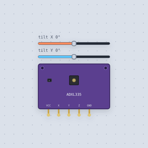
The Accelerometer, ADXL335 analog in brief
What it is, and every setting the properties panel gives it.
The ADXL335 is the simplest accelerometer to wire: three analog outputs, one per axis, and nothing to talk to over a bus. The GY-61 board it usually comes on runs the chip from a 3.3 V regulator, so it takes 5 V from an Arduino, and its outputs are ratiometric: at zero g each sits at half the supply, 1.65 V, and one g moves it by a tenth of the supply, 330 mV. On a 5 V Uno that is about 338 counts at rest and 68 counts per g. Mokxi models a part at rest, so gravity is the only acceleration it feels: tip the board with its two sliders and the 1 g moves off Z onto X and Y, never adding up to more. Each output leaves the chip through 32 kilohms, which is what analogRead() sees. Shakes, bumps, noise and the zero-g spread between real chips are not modeled.
- Family
- Sensors
- Pins
- 5
- tilt_x
- 0
- tilt_y
- 0
5 pins
Named as the editor names them, so a wire lands where you expect it.
How to read an ADXL335 accelerometer with an Arduino
VCC to 5 V and GND to ground, then each axis to an analog input: in the tilt maze, X to A0 and Y to A1. Z is left unwired because a maze on a table only needs two axes. No library is involved: analogRead() on each pin gives the axis directly.
The arithmetic is where people slip. Zero g is not 512 on this board but about 338, half of 3.3 V read on a 5 V scale, and one g is about 68 counts either side of it. The maze treats anything more than a quarter of a g, 17 counts, as a tilt and rolls the dot one cell that way every 150 ms on the 8x8 matrix (DIN on pin 12, CLK on 11, CS on 10). Tip the board with its sliders, steer the dot to the blinking goal and the next maze appears.
On a 3.3 V board the outputs span the ADC’s whole range, so zero g reads near the middle: about 2048 of 4095 on an ESP32’s ADC1 pins, which is where to wire X, Y and Z there.
const int ZERO_G = 338;      // 1.65 V on a 5 V Uno
const int QUARTER_G = 17;    // about 68 counts a g

int direction(int counts) {
  if (counts > ZERO_G + QUARTER_G) return 1;
  if (counts < ZERO_G - QUARTER_G) return -1;
  return 0;
}

int dx = direction(analogRead(A0));
Common Accelerometer, ADXL335 analog errors and fixes
Questions and answers
Does the ADXL335 need a library?
No. It has no bus: each axis is a voltage, read with analogRead(). The only work is subtracting the zero-g level and scaling by the counts per g.
How do I turn an ADXL335 reading into an angle?
Convert each axis to g by subtracting zero g and dividing by the counts per g, then take the arcsine of one axis, or atan2 of two, for the tilt in that direction.
Why is zero g not in the middle of the Arduino’s range?
The GY-61 runs the chip on 3.3 V and its outputs center on half of that supply. An Uno measures against 5 V, so 1.65 V lands at about a third of the scale.
Should I use the ADXL335 or the ADXL345?
The ADXL335 is analog and needs no code beyond analogRead(); the ADXL345 is digital, over I2C or SPI, with more range settings and tap detection. Both have pages here.
What is true about the Accelerometer, ADXL335 analog, here
In its help article’s own words: what the simulation gets right, and where it stops.
Modeled
From the ADXL335 datasheet:
Ratiometric outputs. At 0 g each output sits at half the chip's supply, and 1 g moves it by a tenth of the supply: 300 mV/g at the datasheet's 3 V, and 330 mV/g on the GY-61's 3.3 V. So on a 5 V Uno, 0 g is about 338 counts and 1 g about 68 counts either side.
Gravity. The part is still, so gravity is the only acceleration: tilted, it moves from Z onto X and Y, and the three never add up to more than 1 g.
The output resistance. Each output leaves the chip through 32 kohm, which is what
analogRead() sees.
Not modeled
Shakes, bumps and falls; the chip-to-chip spread of the zero-g level (calibrate a real one flat on the table); noise; and the self-test pin, which the GY-61 does not bring out.
From Accelerometer, ADXL335, in full.
See the Accelerometer, ADXL335 analog in a project
One built-in project uses it. It opens in the editor, already wired.
The boards it is shown on
This board has a built-in project with the Accelerometer, ADXL335 analog in it.
The rest of the bench
Every one of these is drawn and simulated the same way.
Wire up the Accelerometer, ADXL335 analog
Open the editor and push it into the breadboard. It is free, and it runs on your own machine.