VL53L0X time-of-flight sensor
Times a pulse of laser light to the target and back: millimeters over I2C, up to about 1.2 m.
- 6 pins
- 1 setting
- In 1 project
- In 1 lesson
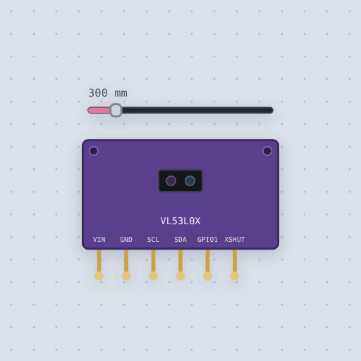
The VL53L0X time-of-flight sensor in brief
What it is, and every setting the properties panel gives it.
The VL53L0X is ST’s laser time-of-flight distance sensor, on the GY-VL53L0XV2, Pololu or Adafruit breakout with six pins: VIN, GND, SCL, SDA, GPIO1 and XSHUT. VIN takes 2.6 to 5.5 V and the board regulates and pulls up the bus, so on an Uno it is 5 V with SDA on A4 and SCL on A5, and on an ESP32 3.3 V with GPIO 21 and 22. It answers at 0x29. Mokxi models the registers the libraries’ ranging path uses: model id 0xEE at 0xC0, single, back-to-back and timed ranging with the default 33 ms timing budget, the interrupt status and the open-drain GPIO1 that goes low when a range is ready, and 8190 with a phase-fail status past 1.2 m, the default mode’s reach on a white target indoors. The slider sets the target from 0 to 2000 mm. A new address written to 0x8A holds until power goes or XSHUT is pulled low. The classic mistake is two sensors on one bus both at 0x29, which a TCS34725 color sensor also claims. Measurement noise, the target’s color, room light, SPAD calibration and the long-range modes are not modeled.
- Family
- Sensors
- Pins
- 6
- noise_mm
- 0
6 pins
Named as the editor names them, so a wire lands where you expect it.
How to use the VL53L0X laser sensor with an Arduino
VIN to 5 V, GND to GND, SDA to A4 and SCL to A5. GPIO1 and XSHUT can stay open: the board pulls XSHUT up, and the laser ruler polls rather than waiting on the interrupt. The sensor answers at 0x29.
With Pololu’s VL53L0X library, call setTimeout(500), then init(), then startContinuous(), and read readRangeContinuousMillimeters() in the loop. Each range takes the default 33 ms. Past about 1.2 m the chip reports 8190, which means nothing came back, so treat that as out of range rather than as a distance. Check timeoutOccurred() too, as the example does.
Two of them on one bus both answer 0x29. Hold one off with XSHUT, give the other a new address, then let the first one up.
On an ESP32, power the board from 3.3 V and use GPIO 21 for SDA and 22 for SCL; VIN takes 2.6 to 5.5 V.
#include <Wire.h>
#include <VL53L0X.h>
VL53L0X sensor;
void setup() {
  Serial.begin(9600);
  Wire.begin();
  sensor.setTimeout(500);
  if (!sensor.init()) while (1) {}
  sensor.startContinuous();
}
void loop() {
  uint16_t mm = sensor.readRangeContinuousMillimeters();
  if (mm >= 8190) Serial.println("out of range");
  else Serial.println(mm);
  delay(200);
}What is true about the VL53L0X time-of-flight sensor, here
In its help article’s own words: what the simulation gets right, and where it stops.
Modeled
ST describes the VL53L0X through its software API rather than a register map, so the model answers the registers the libraries' ranging path uses:
Identity: the model ID 0xEE at 0xC0, which every library checks first.
Measurements take time. Each one takes the default 33 ms timing budget. Single
shot, back to back and timed modes run as written to SYSRANGE_START, and a range
is ready when the interrupt status says so; clearing the interrupt clears it.
Out of range: past about 1.2 m, the default mode's reach for a white target indoors, the chip reports 8190 and a phase-fail status.
A new address written to 0x8A holds until power goes or XSHUT is pulled low,
which is how several sensors share one bus.
Not modeled
The few millimeters of noise a real reading has, and how the target's color and the room's light change the reach. The reference SPAD and temperature calibration ST's full start-up runs, and the long range and high accuracy modes.
From VL53L0X time-of-flight sensor, in full.
See the VL53L0X time-of-flight sensor in a project
One built-in project uses it. It opens in the editor, already wired.
Where it turns up in a lesson
One lesson places it in its own circuit.
The boards it is shown on
This board has a built-in project with the VL53L0X time-of-flight sensor in it.
Arduino libraries for the VL53L0X time-of-flight sensor
Built in, so the sketch compiles with nothing to install. Each page has the calls, the wiring and an example to run.
The rest of the bench
Every one of these is drawn and simulated the same way.
Wire up the VL53L0X time-of-flight sensor
Open the editor and push it into the breadboard. It is free, and it runs on your own machine.