Traffic light module
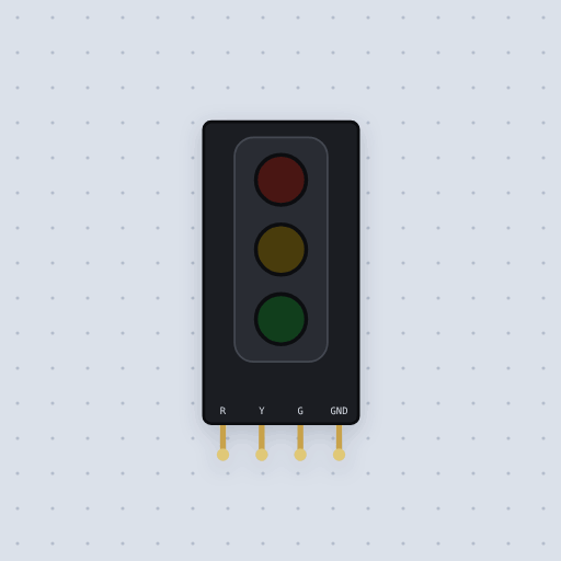
Red, yellow and green LEDs with their resistors on a little board: a pin high lights each.
- 4 pins
- 1 setting
- In 7 projects
- In 2 lessons
The Traffic light module in brief
What it is, and every setting the properties panel gives it.
The traffic light module is a red, a yellow and a green LED in a row on a small board, each with its own resistor, and four pins: R, Y, G and GND. It is the first build in a lot of kits because it needs no breadboard and no resistors of your own: each anode comes out on its own pin through the board’s resistor and the three cathodes share GND. A pin driven high lights its lamp and a pin driven with analogWrite() dims it. The model gives each LED the same diode as the plain LED part, in its own color, with a 220 ohm resistor by default, which is about 15 mA on 5 V. The exact resistors on your board and the relative brightness of the colors are not modeled.
- Family
- Outputs
- Pins
- 4
- resistor
- 220
4 pins
Named as the editor names them, so a wire lands where you expect it.
How to wire a traffic light module to an Arduino
Four wires and nothing else. GND goes to the Uno’s GND, and R, Y and G go to three digital pins: the breathalyzer project uses 4 for red, 3 for yellow and 2 for green. The resistors are already on the board, so the pins connect straight to it. A pin that is HIGH lights its lamp.
In the project the module shows the alcohol level on its three lamps, beside an MQ-3 sensor and a 16x2 LCD. The lamp code is only pinMode() and digitalWrite(), so the module is also the easiest way to learn them: set the three pins as outputs, then turn one on at a time.
On a 3.3 V board the LEDs get less current through the same resistor, so the lamps are a little dimmer. The wiring is the same on every board.
const int GREEN_PIN = 2;
const int YELLOW_PIN = 3;
const int RED_PIN = 4;

void setup() {
  pinMode(GREEN_PIN, OUTPUT);
  pinMode(YELLOW_PIN, OUTPUT);
  pinMode(RED_PIN, OUTPUT);
  digitalWrite(GREEN_PIN, HIGH);   // green lamp on
}

void loop() {}
Common Traffic light module errors and fixes
Questions and answers
Does a traffic light LED module need resistors?
No. Each LED has its own resistor on the board, 220 ohm by default in the model, so the pins go straight to the Arduino.
How do you dim a lamp on the traffic light module?
Drive its pin with analogWrite() on a PWM pin. The lamp dims as the eye would see it.
Which pin is the ground on a traffic light module?
GND. It is the common cathode of the three LEDs, and it goes to the board’s ground.
What is true about the Traffic light module, here
In its help article’s own words: what the simulation gets right, and where it stops.
Modeled
The LEDs. Each is the same diode as the led part, in its own color, so red,
yellow and green light at the currents a real LED does on the same resistor.
The common ground. All three cathodes meet at GND; with it unwired nothing
lights.
Not modeled
The exact resistor on your board, and the LEDs' brightness against each other (a real green LED often looks brighter than the red at the same current).
From Traffic light module, in full.
See the Traffic light module in a project
7 built-in projects use it. Each opens in the editor, already wired.
Where it turns up in a lesson
2 lessons place it in their own circuits.
The boards it is shown on
This board has a built-in project with the Traffic light module in it.
The rest of the bench
Every one of these is drawn and simulated the same way.
Wire up the Traffic light module
Open the editor and push it into the breadboard. It is free, and it runs on your own machine.