LED and key board, TM1638
Eight digits, eight LEDs and eight buttons on three wires. STB low, bytes least significant bit first.
- 5 pins
- In 1 project
- In 1 lesson
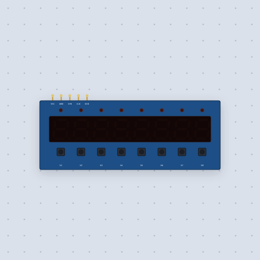
The LED and key board, TM1638 in brief
What it is, and where it sits on the bench.
The TM1638 LED&KEY board has eight seven-segment digits, eight LEDs and eight buttons on three wires: STB, CLK and DIO, with VCC and GND at 5 V. STB, the strobe, is low for the length of each command. Data is taken on the rising edge of CLK, and DIO carries data both ways: the board drives it to send and the chip pulls it low to answer a key read. The chip holds the picture and scans the buttons itself, so a sketch only sends bytes, which makes it the usual front panel for clocks, counters and scoreboards. The model follows the datasheet’s data, address and display control commands, with sixteen bytes of display RAM. Press the buttons with the pointer.
- Family
- Displays
- Pins
- 5
5 pins
Named as the editor names them, so a wire lands where you expect it.
How to use a TM1638 LED&KEY board with an Arduino
The board takes three signal wires and 5 V. STB goes to pin 4, CLK to pin 6 and DIO to pin 7, with GND on the Uno’s ground and VCC on 5 V. The sketch uses Gavin Lyons’ TM1638plus library, which Mokxi ships as TM1638plus.h, and its constructor takes the strobe, clock and data pins in that order.
readButtons() returns a byte with one bit for each of the eight buttons, bit 0 being S1. This sketch lights the LED over each held button, counts presses and shows the count and the last button on the eight digits. Click the buttons with the pointer.
#include <TM1638plus.h>

TM1638plus tm(4, 6, 7);   // STB, CLK, DIO

void setup() {
  tm.displayBegin();
  tm.brightness(2);
  tm.displayText("LED KEY ");
}

void loop() {
  uint8_t buttons = tm.readButtons();     // bit 0 is S1
  tm.setLEDs((uint16_t)buttons << 8);     // the LED over each button
  delay(20);
}
Common LED and key board, TM1638 errors and fixes
Questions and answers
How many pins does the TM1638 board need?
Three signal pins, STB, CLK and DIO, plus 5 V and ground.
How many buttons and LEDs does the LED&KEY board have?
Eight of each, with eight seven-segment digits.
Which library does Mokxi use for the TM1638?
Gavin Lyons’ TM1638plus, as TM1638plus.h.
What is true about the LED and key board, TM1638, here
In its help article’s own words: what the simulation gets right, and where it stops.
Modeled
From the TM1638 datasheet: the data, address and display control commands; bytes
least significant bit first on the rising edge of CLK; auto-increment and fixed
addressing; sixteen bytes of display RAM, the even ones the digits and bit 0 of
the odd ones the LEDs on this board; the eight pulse widths; display off keeping
the RAM. A key read returns four bytes on DIO, open drain against the board's
pull-up, with the board's buttons wired so the usual byte_i << i fold gives one
bit per button.
Not modeled
The multiplexing (all eight digits are drawn lit at once), the 1 MHz clock limit, test mode, and the bicolor LEDs of the other TM1638 boards.
From TM1638 LED and key board, in full.
See the LED and key board, TM1638 in a project
One built-in project uses it. It opens in the editor, already wired.
Where it turns up in a lesson
One lesson places it in its own circuit.
The boards it is shown on
This board has a built-in project with the LED and key board, TM1638 in it.
Arduino libraries for the LED and key board, TM1638
Built in, so the sketch compiles with nothing to install. Each page has the calls, the wiring and an example to run.
The rest of the bench
Every one of these is drawn and simulated the same way.
Wire up the LED and key board, TM1638
Open the editor and push it into the breadboard. It is free, and it runs on your own machine.