12864 LCD, ST7920
The blue 128x64 LCD from 3D printer kits: three-wire serial or 8-bit parallel, text and graphics, for U8g2.
- 20 pins
- In 1 project
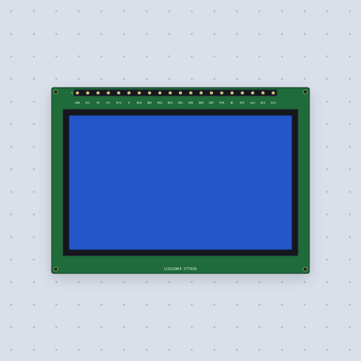
The 12864 LCD, ST7920 in brief
What it is, and where it sits on the bench.
- Family
- Displays
- Pins
- 20
20 pins
Named as the editor names them, so a wire lands where you expect it.
V0. Leave it unwired.BLA to 5 V, BLK to ground.BLA to 5 V, BLK to ground.What is true about the 12864 LCD, ST7920, here
In its help article’s own words: what the simulation gets right, and where it stops.
Modeled
Two buses. With PSB high it is a parallel bus: a write is latched on the falling
edge of E, a read is on DB0 to DB7 while E is high, and the function set's
DL bit picks eight bits or four (high nibble first on DB7 to DB4). Reads work,
with the dummy read after every address set, and an instruction read returns the busy
flag and the address counter. With PSB low it is the serial bus, write only:
SID is sampled on the rising edge of SCLK while CS is high, a transfer starts
with five ones then RW, RS and a zero (0xF8 for an instruction, 0xFA for
data), and each byte comes as two bytes, the high nibble then the low one, in the top
four bits. CS low drops a byte half sent.
Both instruction sets. Basic: clear, home, entry mode, display on and off, cursor
move, function set, CGRAM and DDRAM address. Extended: standby, scroll or IRAM select,
line reverse, sleep, graphics on (G), the vertical scroll address and the graphic RAM
address. As the datasheet says, an instruction that changes RE changes nothing else,
which is why U8g2 sends 0x3E twice.
The 256x32 layout. The chip draws 256 dots by 32 rows, and the module folds that in half: rows 0 to 31 of graphic RAM, words 0 to 7, are the top half of the glass, and words 8 to 15 are the bottom half. Set the vertical address, then the horizontal one, then write two bytes a word; the horizontal address steps after each word and wraps from 15 to 0 on the same row.
Text mode. DDRAM lines start at 0x80, 0x90, 0x88 and 0x98 for the four
text rows of 16 characters. A two-byte word is two 8x16 half-width characters (codes
0x02 to 0x7F) or one 16x16 character; codes 0x0000 to 0x0006 are the four
characters you define in CGRAM. Clear fills DDRAM with spaces. Text and graphics show
together once G is set.
Not modeled
The half-width font is Mokxi's own 5x8 font drawn twice as tall in the 8x16 cell, not
the ROM's glyphs, and the ROM's symbols below 0x20 draw blank. The 8192 Chinese
characters are not in the model: one shows as an empty box. Where text and graphics
overlap, the model combines them with XOR, which is how these modules are reported to
behave; the datasheet does not say. The cursor, blink and display shift are kept but
not drawn, and the icon RAM shows nothing (this module has no icon segments). An
instruction sent while the busy flag is set is still taken, where a real chip may miss
it. The contrast is the module's trimmer, shown at its best, and the graphic RAM
starts blank rather than random.
From ST7920 12864 graphic LCD, in full.
See the 12864 LCD, ST7920 in a project
One built-in project uses it. It opens in the editor, already wired.
The boards it is shown on
This board has a built-in project with the 12864 LCD, ST7920 in it.
The rest of the bench
Every one of these is drawn and simulated the same way.
Wire up the 12864 LCD, ST7920
Open the editor and push it into the breadboard. It is free, and it runs on your own machine.