RF receiver, XY-MK-5V
Hears every FS1000A on the canvas, and hisses random noise when nothing sends, like the real one.
- 5 pins
- 1 setting
- In 1 project
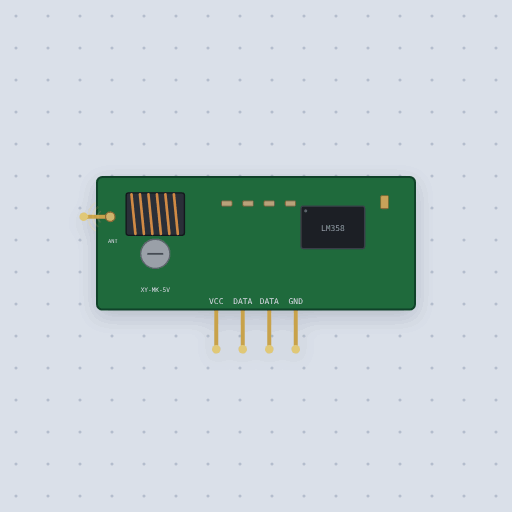
The RF receiver, XY-MK-5V in brief
What it is, and every setting the properties panel gives it.
The XY-MK-5V is the 433 MHz receiver half of the kit pair: a superregenerative receiver and an LM358 that turns the carrier into a logic level on DATA, high while a transmitter’s carrier is on. Its pins are VCC, DATA, DATA and GND, the two DATA pins one line, rated for 5 V; the LM358’s high stops about 1.5 V short of VCC, so on 3.3 V it is too weak for a 3.3 V board. With nothing sending it has no squelch and DATA toggles at random, which Mokxi models after 20 ms without a carrier. That noise is why rc-switch takes a code only after it arrives twice and RH_ASK waits for a preamble, a start symbol and a CRC. Use enableReceive(0) for pin 2 on an Uno, or RH_ASK on pin 11.
- Family
- Clocks and links
- Pins
- 5
- noise
- true
5 pins
Named as the editor names them, so a wire lands where you expect it.
DATA.How to use the XY-MK-5V 433 MHz receiver with an Arduino
Wire VCC to 5 V, GND to GND and either DATA pin to pin 2, the Uno’s interrupt 0, and leave the antenna pad alone. DATA is high while a carrier is heard; between codes it is random noise, as on a real bench, which the logic analyzer shows.
With rc-switch, call enableReceive(0) once in setup(), then check available() in loop() and read getReceivedValue(). rc-switch only takes a code that arrives twice the same way, so the noise never prints. Run it at 5 V: on 3.3 V the module’s high is under 2 V, which an ESP32 may read as low.
On an ESP32 or a Pico, pass the pin itself to enableReceive(). Give the module 5 V and put a divider on DATA, because those boards are not 5 V tolerant.
mySwitch.enableReceive(0); // pin 2
if (mySwitch.available()) {
  Serial.println(mySwitch.getReceivedValue());
  mySwitch.resetAvailable();
}What is true about the RF receiver, XY-MK-5V, here
In its help article’s own words: what the simulation gets right, and where it stops.
Not modeled
Distance, walls, signal strength and interference: every transmitter on the canvas is heard at full strength. The edges come out when the carrier switches, where a real one lags by some tens of microseconds and its pulse widths wander. The tuning coil is assumed set to 433.92 MHz.
From 433 MHz receiver, XY-MK-5V, in full.
See the RF receiver, XY-MK-5V in a project
One built-in project uses it. It opens in the editor, already wired.
The boards it is shown on
This board has a built-in project with the RF receiver, XY-MK-5V in it.
The rest of the bench
Every one of these is drawn and simulated the same way.
Wire up the RF receiver, XY-MK-5V
Open the editor and push it into the breadboard. It is free, and it runs on your own machine.