Real-time clock, PCF8563
A clock and calendar at I2C 0x51 with an alarm, a countdown timer and a VL flag, for RTClib’s RTC_PCF8563.
- 6 pins
- 2 settings
- In 1 project
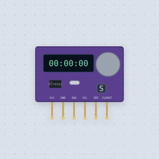
The Real-time clock, PCF8563 in brief
What it is, and every setting the properties panel gives it.
- Family
- Clocks and links
- Pins
- 6
- start
- 2026-01-01 12:00:00
- lostpower
- false
6 pins
Named as the editor names them, so a wire lands where you expect it.
What is true about the Real-time clock, PCF8563, here
In its help article’s own words: what the simulation gets right, and where it stops.
Modeled
The registers. Sixteen of them, from NXP's data sheet: two control and status
registers, seven time registers from 0x02 in BCD (seconds with VL in bit 7,
minutes, hours in 24-hour form, day of the month, weekday 0 to 6, month with the
century bit, year), four alarm registers, CLKOUT_control, Timer_control and
Timer. The pointer steps after each byte and wraps from 0x0F to 0x00, and the
registers come up as the data sheet's reset table says.
The calendar. One tick a second. Every year divisible by four is a leap year, 00 included, and the century bit flips when the years roll from 99 to 00. While a transfer reads or writes the time registers the counters are held, and a tick that came meanwhile is taken at the STOP, as the data sheet describes.
STOP. Setting STOP in Control_status_1 holds the clock. Clearing it starts
the first tick 0.507813 s later, then one every second.
The alarm. Minute, hour, day and weekday, each on when its top bit is clear. When
every enabled one matches for the first time, AF is set, and with AIE the INT
pin goes low until a sketch clears AF.
The timer. An eight-bit countdown at 4096 Hz, 64 Hz, 1 Hz or once a minute. At
the end of each countdown it sets TF and starts again. With TIE, INT follows
TF, or with TI_TP gives one short pulse a countdown. Writing 0 clears AF or
TF and writing 1 leaves it, so clearing one never clears the other.
Not modeled
The 32.768 kHz CLKOUT, which is too fast to simulate cheaply: at that setting the
pin is let go. The EXT_CLK test mode and the power-on reset override: their bits are
kept and change nothing. The voltage-low detector: with the coin cell fitted the chip
never sees its supply drop, so VL comes only from the lostpower property. Below
1.8 V the chip leaves the bus and keeps time. The crystal's drift: this clock is
exact.
From PCF8563 real-time clock, in full.
See the Real-time clock, PCF8563 in a project
One built-in project uses it. It opens in the editor, already wired.
The boards it is shown on
This board has a built-in project with the Real-time clock, PCF8563 in it.
Arduino libraries for the Real-time clock, PCF8563
Built in, so the sketch compiles with nothing to install. Each page has the calls, the wiring and an example to run.
The rest of the bench
Every one of these is drawn and simulated the same way.
Wire up the Real-time clock, PCF8563
Open the editor and push it into the breadboard. It is free, and it runs on your own machine.