Optocoupler, 4N35
An infrared LED and a phototransistor in one DIP-6, with no wire between them: switch a circuit you cannot connect to.
- 6 pins
- 1 setting
- In 1 project
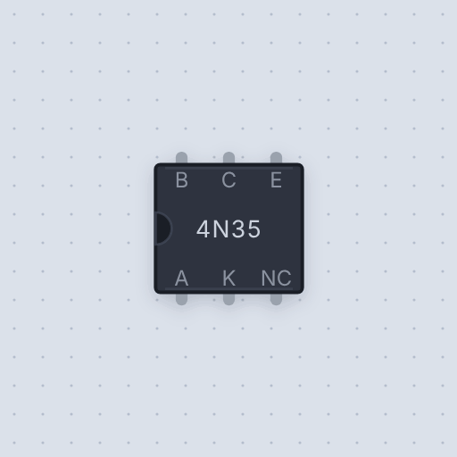
The Optocoupler, 4N35 in brief
What it is, and every setting the properties panel gives it.
An optocoupler is an infrared LED and a phototransistor sealed in one black DIP-6, facing each other across a gap of clear plastic. Current through the LED makes light, the light turns the transistor on, and the two sides share no wire, so the circuit on the transistor side can have its own supply and ground. That is the whole point, and it is how the Arduino Starter Kit’s Hacking Buttons project presses another gadget’s button. The Mokxi part is the 4N35, and the four-pin PC817 on relay modules works the same way. The LED is an infrared one, 1.2 V at 10 mA and about 1.35 V at 50 mA. The transistor’s light comes from the LED current, so its collector current is the CTR percentage times the LED current, 120 percent by default, and if asked for less it saturates at about 0.1 V. The base pin is left open, and switching time, aging and the isolation voltage are not modeled.
- Family
- Timers and analog
- Pins
- 6
- ctr
- 120
6 pins
Named as the editor names them, so a wire lands where you expect it.
How to use a 4N35 optocoupler with an Arduino
The project keeps two circuits apart. On the Uno side, pin 2 goes through a 220 ohm resistor to A, the LED’s anode, and K goes to the Uno’s ground. That is about 17 mA. On the other side, two AA cells, a 330 ohm resistor and a red LED stand in for the gadget, and the transistor’s C and E go where its button would: collector toward the more positive side. Every two seconds the sketch takes pin 2 high, the infrared LED lights, and the far LED comes on with no wire between the two.
The LED is an LED, so it wants its resistor. Without one a pin pushes as much current as it can, far past the rating. Pin 3 is not connected on the real part either, and the base, pin 6, is left open in the model, so anything wired to B has no effect.
The CTR, current transfer ratio, is the collector current per milliamp of LED current at the datasheet’s test point. Vendors guarantee at least 100 percent, and the model defaults to 120. A transistor asked for less than that saturates, about 0.1 V collector to emitter, which is the pressed state a button needs. It is a transistor, not a contact: wired backward across a button it barely conducts, and it is good for tens of milliamps, so to switch more use it to drive a transistor or a relay.
On a 3.3 V board use a smaller resistor for the same LED current: (3.3 V minus about 1.2 V) over 10 mA is about 210 ohms, so 220 ohms gives roughly 10 mA.
const int OPTO_PIN = 2;

void setup() {
  pinMode(OPTO_PIN, OUTPUT);
}

void loop() {
  digitalWrite(OPTO_PIN, HIGH);   // "press"
  delay(300);
  digitalWrite(OPTO_PIN, LOW);    // "release"
  delay(1700);
}
Common Optocoupler, 4N35 errors and fixes
Questions and answers
What is an optocoupler used for?
To pass a signal between two circuits with no electrical connection. The LED lights, the phototransistor conducts, and the two sides can have separate supplies and grounds.
What is CTR?
The current transfer ratio: collector current per milliamp of LED current, in percent, at 10 mA and 10 V. Every vendor guarantees at least 100 percent for a 4N35. The model defaults to 120.
Why does the LED need a resistor?
It is an infrared LED with a forward drop of about 1.2 V. Without a resistor, a pin drives current limited only by the pin, far above the part’s rating.
Does the model enforce the isolation rating?
No. The two sides are separate circuits with no path between them, and the isolation voltage is unlimited in the simulation. A real part has a limit.
What is true about the Optocoupler, 4N35, here
In its help article’s own words: what the simulation gets right, and where it stops.
Modeled
Isolation. The LED side and the transistor side are separate circuits with no path between them, so each can have its own ground.
The LED's drop. It is an infrared GaAs LED, not a visible one: 1.2 V at 10 mA and about 1.35 V at 50 mA, from the 4N35 sheets (1.5 V maximum). Under about 1 V it passes almost nothing.
The current transfer ratio. The transistor's light comes from the LED current,
solved in the same step, so its collector current in the active region is ctr
times the LED current at the test point: every vendor's 4N35 guarantees at least
100 %, and the default of 120 % is an assumption just above that floor. A
transistor asked for less than that saturates, about 0.1 V from collector to
emitter, which is the "pressed" state a button circuit needs.
It is a transistor, not a contact. Wired backwards across a button (emitter to the positive side) it barely conducts, and it only carries current one way.
Not modeled
The base pin: the 4N35 brings the transistor's base out on pin 6 so a resistor to
the emitter can speed up switching. Here the base is open inside, as in most hobby
circuits, and anything wired to B has no effect.
The switching time (a few microseconds), the CTR's fall at very low and very high LED currents and as the part ages, temperature, and the isolation voltage, which here is unlimited.
From Optocoupler (4N35), in full.
See the Optocoupler, 4N35 in a project
One built-in project uses it. It opens in the editor, already wired.
The boards it is shown on
This board has a built-in project with the Optocoupler, 4N35 in it.
The rest of the bench
Every one of these is drawn and simulated the same way.
Wire up the Optocoupler, 4N35
Open the editor and push it into the breadboard. It is free, and it runs on your own machine.