NLSF595 tri-color LED driver
A 595 whose outputs sink current: eight cathodes of common-anode RGB LEDs on three pins.
- 16 pins
- In 1 project
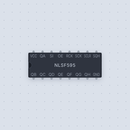
The NLSF595 tri-color LED driver in brief
What it is, and where it sits on the bench.
- Family
- Logic
- Pins
- 16
16 pins
Named as the editor names them, so a wire lands where you expect it.
SI.SI.What is true about the NLSF595 tri-color LED driver, here
In its help article’s own words: what the simulation gets right, and where it stops.
Modeled
From the NLSF595 datasheet (NLSF595/D): the function table (shift on the rising
edge of SCK, latch on the rising edge of RCK, SCLR clearing the shift
register only, OE high floating the outputs), the double-buffered outputs, the
push-pull SQH, and the pin positions of the TSSOP-16. The outputs pull low for
a stored 0 and let go for a 1.
Not modeled
The output's exact on-voltage (0.6 V at 25 mA at most, on a 4.5 V supply), the overvoltage-tolerant inputs, and the 25 MHz clock limit.
From NLSF595 tri-color LED driver, in full.
See the NLSF595 tri-color LED driver in a project
One built-in project uses it. It opens in the editor, already wired.
The boards it is shown on
This board has a built-in project with the NLSF595 tri-color LED driver in it.
The rest of the bench
Every one of these is drawn and simulated the same way.
Wire up the NLSF595 tri-color LED driver
Open the editor and push it into the breadboard. It is free, and it runs on your own machine.