MAX30102 pulse oximeter
Red and infrared light through a fingertip: the pulse and the blood oxygen, over I2C.
- 7 pins
- 1 setting
- In 2 projects
- In 1 lesson
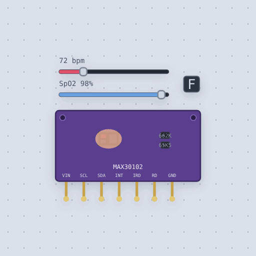
The MAX30102 pulse oximeter in brief
What it is, and every setting the properties panel gives it.
The MAX30102 is a pulse oximeter and heart-rate sensor: a red and an infrared LED shine into a fingertip and a photodiode measures what comes back. The common breakout brings out VIN, SCL, SDA, INT, IRD, RD and GND; VIN takes 1.8 to 5.5 volts, the I2C address is fixed at 0x57, and IRD and RD should be left open. On an Uno SDA and SCL go to A4 and A5, on an ESP32 to GPIO 21 and 22. Mokxi models the datasheet’s registers: part ID 0x15, heart-rate, SpO2 and multi-LED modes, LED currents at 0.2 mA a step, a 32-sample FIFO with averaging and rollover, 15 to 18 bit resolution by pulse width, and the open-drain interrupts. The SparkFun MAX30105.h library works, and at its defaults a finger reads about 100 000 counts of IR. Sliders set the heart rate from 30 to 220 beats a minute and SpO2 from 70 to 100 percent, and a button places the finger. The usual mistake is storing 18-bit samples in 16-bit variables on an Uno. The pulse is synthesized, with no noise, motion or ambient light.
- Family
- Sensors
- Pins
- 7
- temperature
- 31
7 pins
Named as the editor names them, so a wire lands where you expect it.
How to use the MAX30102 with an Arduino
Wire VIN to 5 V, GND to GND, SDA to A4 and SCL to A5, and leave INT, IRD and RD open. Include MAX30105.h, the SparkFun library that drives the MAX30102 too, call sensor.begin(Wire, I2C_SPEED_FAST), then sensor.setup() with the LED current, averaging, mode, sample rate, pulse width and ADC range.
The Uno has room for a hundred samples of each color only as 16-bit numbers, so the example runs the LEDs at 4 mA to keep readings under 65536. It then collects four seconds at 25 samples a second before calling the SpO2 algorithm; give it fewer and it reports nothing valid. Press F on the part to take the finger off.
The breakout takes 1.8 to 5.5 V on VIN, so on an ESP32 power it from 3.3 V and use GPIO 21 and 22 for SDA and SCL.
What is true about the MAX30102 pulse oximeter, here
In its help article’s own words: what the simulation gets right, and where it stops.
Modeled
From the MAX30102 datasheet:
The registers: the part ID 0x15, the mode (heart rate, SpO2, or the multi-LED slots), the ADC range, sample rate and pulse width, the LED currents at 0.2 mA a step, and a reset that puts them all back.
The FIFO: 32 samples of three bytes a channel, with its read and write pointers, the overflow counter, averaging from 1 to 32 samples, and rollover on or off. The pulse width sets the resolution, 15 to 18 bits, left justified.
The interrupts: new sample and almost full, the die temperature, and power
ready, on the open-drain INT pin.
The light: a fingertip sends back a fixed share of each LED's light, so the reading scales with the LED current and the ADC range the way it does on the chip, and the libraries' "finger present" level, about 100 000 counts of IR at their defaults, is where it should be. With no finger a few hundred counts come back.
Not modeled
The pulse is drawn, not recorded: a dip once a beat of 2% of the IR level (the perfusion index), with a quick fall and a slower recovery. The red dips by R times as much, from SpO2 = 110 - 25 R, the linear calibration most oximeter notes give; real oximeters are calibrated per design against blood samples. There is no noise, no motion, and no ambient light, the MAX30102's third slot reads 0 because it has no green LED, and any sample rate and pulse width combination runs, including the ones the datasheet rules out.
From MAX30102 pulse oximeter, in full.
See the MAX30102 pulse oximeter in a project
2 built-in projects use it. Each opens in the editor, already wired.
Where it turns up in a lesson
One lesson places it in its own circuit.
The boards it is shown on
This board has a built-in project with the MAX30102 pulse oximeter in it.
Arduino libraries for the MAX30102 pulse oximeter
Built in, so the sketch compiles with nothing to install. Each page has the calls, the wiring and an example to run.
The rest of the bench
Every one of these is drawn and simulated the same way.
Wire up the MAX30102 pulse oximeter
Open the editor and push it into the breadboard. It is free, and it runs on your own machine.