UV and light, LTR-390
The UV index and the visible light from one sensor, 13 to 20-bit counts at gain 1 to 18.
- 5 pins
- 2 settings
- In 1 project
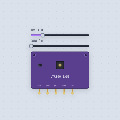
The UV and light, LTR-390 in brief
What it is, and every setting the properties panel gives it.
The Lite-On LTR-390UV is a digital sensor that reads the UV index or the visible light level over I2C at address 0x53, one at a time. It offers 13 to 20 bit readings at a gain of 1 to 18, so the same light can be read with more or fewer counts. The UV index is the number the weather forecast gives, 0 at night to 11 and more at noon in summer, which makes the part a natural sunburn warning. The Mokxi model exposes two properties, uvi for the UV index and lux for visible light, changed with sliders. It reads through Adafruit's library, shipped as Adafruit_LTR390.h. The model leaves out the interrupt pin, which it holds high-Z, the window factor of a cover over the sensor, and the spectral response. On real hardware you would set MAIN_CTRL for UV or light mode and MEAS_RATE and GAIN for resolution and gain, but in the simulator the sliders are what matter.
- Family
- Sensors
- Pins
- 5
- lux
- 300
- uvi
- 3
5 pins
Named as the editor names them, so a wire lands where you expect it.
How to use the LTR-390 UV sensor with an Arduino Uno
The example project is a hiking compass built on an Arduino Uno. An LSM303AGR gives the compass heading and the tilt, and the LTR-390 gives the sun's UV index, with a warning printed at 3 or more. The LTR-390's VIN goes to the Uno's 5V pin, GND to GND, SCL to A5 and SDA to A4, the Uno's I2C lines.
The sketch includes Adafruit_LTR390.h and creates an Adafruit_LTR390 object. In setup it calls uv.begin(), then sets UV mode with setMode(LTR390_MODE_UVS), a gain of 18 with setGain(LTR390_GAIN_18), and 18 bit resolution with setResolution(LTR390_RESOLUTION_18BIT). In loop it calls uv.getUVI() and prints the UV index to one decimal place; at 3 or more it prints a sun cream warning.
With default settings, the serial monitor printed: "Hiking compass", "heading 45 tilt 0 UV 2.0". The heading of 45 comes from the magnetometer, the tilt of 0 means the board is flat, and the UV index of 2.0 is below 3, so no warning is printed.
After changing uvi to 14, the serial monitor printed: "heading 45 tilt 0 UV 14.0", "Sun cream". The UV reading followed the new setting and crossed the threshold of 3, so the sun cream warning appeared. You can drag the UV slider past 3 yourself, or tip the board with the roll slider and watch the heading and tilt change.
// Hiking compass: an LSM303AGR reads which way is down and which way is
// north, and an LTR-390 reads the sun's UV index, two things worth knowing
// on a hill.
//
//   LSM303AGR   SDA -> SDA   SCL -> SCL
//   LTR-390     SDA -> A4    SCL -> A5
//
// The compass heading comes from the magnetometer's two level axes, so it is
// only right while the board is flat; the accelerometer says how far it is
// tipped. A UV index of 3 or more wants sun cream.
//
// Things to try. Drag the heading slider round. Tip the board with the
// roll slider. Drag the UV slider past 3.

#include <Wire.h>
#include <Adafruit_LSM303_Accel.h>
#include "Adafruit_LTR390.h"

const uint8_t MAG = 0x1E;

Adafruit_LSM303_Accel_Unified accel(1);
Adafruit_LTR390 uv;

void setup() {
  Serial.begin(9600);
  Wire.begin();
  if (!accel.begin()) {
    Serial.println("No LSM303");
  }
  // The magnetometer half: continuous at 10 Hz.
  Wire.beginTransmission(MAG);
  Wire.write(0x60);
  Wire.write(0x00);
  Wire.endTransmission();
  uv.begin();
  uv.setMode(LTR390_MODE_UVS);
  uv.setGain(LTR390_GAIN_18);
  uv.setResolution(LTR390_RESOLUTION_18BIT);
  Serial.println("Hiking compass");
}

void loop() {
  delay(200);
  int16_t m[3];
  Wire.beginTransmission(MAG);
Common UV and light, LTR-390 errors and fixes
Questions and answers
what is the ltr390 i2c address
The LTR-390 talks over I2C at 0x53.
can the ltr390 read uv and light at the same time
No. It reads the UV index or the visible light, one at a time.
what voltage does the ltr390 need
It takes 3 to 5 V on VIN, so the Uno's 5V pin works.
does the ltr390 model have an interrupt
No. The INT pin, the threshold interrupt, is left high-Z by the model.
What is true about the UV and light, LTR-390, here
In its help article’s own words: what the simulation gets right, and where it stops.
Not modeled
The interrupt, the window factor of a cover over the sensor, and the spectral response.
From LTR-390 UV and light sensor, in full.
See the UV and light, LTR-390 in a project
One built-in project uses it. It opens in the editor, already wired.
The boards it is shown on
This board has a built-in project with the UV and light, LTR-390 in it.
The rest of the bench
Every one of these is drawn and simulated the same way.
Wire up the UV and light, LTR-390
Open the editor and push it into the breadboard. It is free, and it runs on your own machine.