Part
LM386 audio amplifier
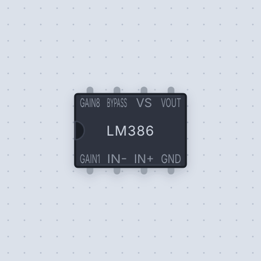
A speaker amplifier in a DIP-8: gain 20, or 200 with 10 uF from pin 1 to 8, output centered on half the supply.
- 8 pins
- In 1 project
Drawn live by the editor's own code, at the size you see it.
At a glance
The LM386 audio amplifier in brief
What it is, and where it sits on the bench.
- Family
- Timers and analog
- Pins
- 8
Pins
8 pins
Named as the editor names them, so a wire lands where you expect it.
Input7
- GAIN1
- IN-
- IN+
- GND
- VS
- BYPASS
- GAIN8
Input or output1
- VOUT
How it is modeled
What is true about the LM386 audio amplifier, here
In its help article’s own words: what the simulation gets right, and where it stops.
Not modeled
- Distortion. The data sheet's 0.2% at 125 mW is a clean output here.
- Supply current against supply voltage. The 4 mA is drawn as a resistance, so it is right at 6 V and grows with the supply: 8 mA on 12 V, where a real one draws about 4.7 mA.
- Input bias current. A real one's open inputs float to about 12.5 mV; here they sit at 0 V.
- Heat and damage. Nothing burns out past the 15 V absolute maximum supply, the ±0.4 V input rating or the package's power limit. An input that is too big clips the output instead.
- Oscillation. A real LM386 is only stable at gains over 9 and can oscillate on a long-wired breadboard without the 10 ohm and 0.05 uF network from pin 5 to ground. The model is always stable.
- Loudness. The speaker part shows the note it hears, not how loud it is.
From LM386 audio amplifier, in full.
Projects
See the LM386 audio amplifier in a project
One built-in project uses it. It opens in the editor, already wired.
Boards
The boards it is shown on
This board has a built-in project with the LM386 audio amplifier in it.
More parts
The rest of the bench
Every one of these is drawn and simulated the same way.
Full-size breadboard
A real 0.1 inch grid with the rails and the center channel, 63 columns wide.
Jumper wires
Drag from any pin or hole to any other. Corners snap, and you can drag them.
Power
A supply rail at the voltage you choose.
Ground
The other end of every circuit.
LED
Lights when current flows. Five colors, and the brightness is what your eye would see.
Filament lamp
A tungsten bulb in a holder: an inrush when it is switched on cold, tens of milliseconds to warm up, and dim on half its voltage.
Resistor
Any value you like, with the color bands drawn to match.
ESP32-C3-DevKitM-1
A RISC-V board that runs your firmware at 160 MHz on the real memory map.
Pushbutton
A 12 mm tactile switch. Hold it while the simulation runs.
Raspberry Pi Pico
The RP2040 board on our own Cortex-M0+ core. Pick a program and press Run.
Raspberry Pi Pico W
Raspberry Pi Pico W (RP2040). The same board and the same pinout as a Pico, with the CYW43439 on it. The WiFi is simulated (no radio; real internet through the Cloud panel’s switch), and the on-board LED, which hangs off that chip rather than off GP25, is driven through the same path. Everything else is the Pico.
Raspberry Pi 4 Model B
Raspberry Pi 4 Model B: the 40-pin header, driven by main.py with RPi.GPIO or gpiozero.
Wire up the LM386 audio amplifier
Open the editor and push it into the breadboard. It is free, and it runs on your own machine.