Laser module, KY-008
A red laser diode behind a resistor between S and GND: S high lights the beam.
- 3 pins
- 1 setting
- In 1 project
- In 2 lessons
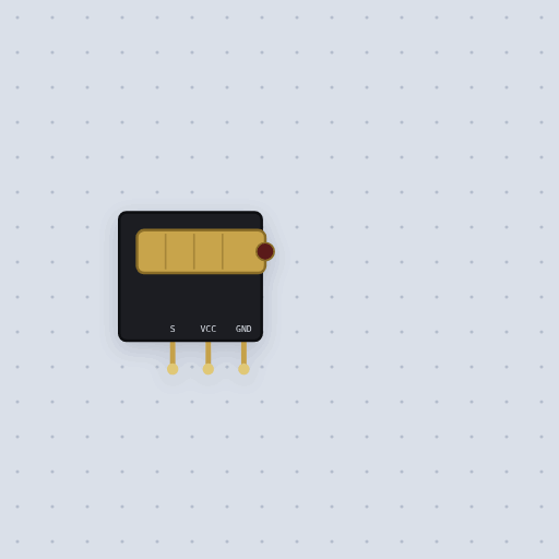
The Laser module, KY-008 in brief
What it is, and every setting the properties panel gives it.
The KY-008 is a 650 nm red laser diode in a brass barrel on a three-pin board. The diode and its resistor sit in series between S and GND, so the signal pin is the supply: a pin driven high runs the laser, low turns it off and analogWrite() dims it. The middle pin, VCC, is not connected on most modules and not in the model. The resistor property is the series resistor, 100 ohm by default, an assumption because the boards are sold without a schematic: a 5 V pin runs the beam at full brightness and a 3.3 V pin at a little over half. Treat any real laser module with the care a laser deserves.
- Family
- Outputs
- Pins
- 3
- resistor
- 100
3 pins
Named as the editor names them, so a wire lands where you expect it.
How to wire a KY-008 laser module to an Arduino
Two wires for the laser: S to pin 7 and GND to GND. The laser runs from the pin itself, so the pin is the supply. The pan servo’s signal is on pin 9 and the tilt servo’s on pin 10, with a button on pin 2 to GND using INPUT_PULLUP, and 5 V and ground rails for the servos and the laser.
A round is a minute of the dot wandering around the floor: pick a spot, glide to it a degree at a time, pause, pick another. Then the laser goes off and the servos rest until the button asks for another round. The tilt never goes above 60 degrees from straight down, so the dot stays on the floor and out of anyone’s eyes. Keep a real laser pointed away from eyes the same way.
A 3.3 V pin runs the beam at a little over half brightness through the default 100 ohm. Use a smaller resistor if you need more, within the pin’s current limit.
#include <Servo.h>

const int LASER = 7;
const int PAN = 9;
const int TILT = 10;

Servo pan, tilt;

void setup() {
  pinMode(LASER, OUTPUT);
  pan.attach(PAN);
  tilt.attach(TILT);
  digitalWrite(LASER, HIGH);
}

void loop() {}
Common Laser module, KY-008 errors and fixes
Questions and answers
Does the KY-008 need a resistor?
It has one on the board, in series with the diode, 100 ohm by default in the model. The signal pin is the supply.
How do I dim a laser module?
Drive S with analogWrite() on a PWM pin.
What is the middle pin of the KY-008?
VCC, which is not connected on most modules and not in the model.
What is true about the Laser module, KY-008, here
In its help article’s own words: what the simulation gets right, and where it stops.
Modeled
The supply is the signal. There is no driver on the board: the diode's current
comes from S itself, the way it does on the real module.
Dimming. The brightness follows the average of a PWM signal, as an eye sees it.
Not modeled
The lasing threshold (a real diode below it glows dimly instead of lasing), the light's power, and the beam's spread.
From Laser module, KY-008, in full.
See the Laser module, KY-008 in a project
One built-in project uses it. It opens in the editor, already wired.
Where it turns up in a lesson
2 lessons place it in their own circuits.
The boards it is shown on
This board has a built-in project with the Laser module, KY-008 in it.
The rest of the bench
Every one of these is drawn and simulated the same way.
Wire up the Laser module, KY-008
Open the editor and push it into the breadboard. It is free, and it runs on your own machine.