IR distance sensor, Sharp GP2Y0A21
10 to 80 cm by triangulation: VO falls from 2.3 V at 10 cm to 0.4 V at 80, a reading every 38 ms. Also the GP2Y0A02, GP2Y0A41 and GP2Y0A710.
- 3 pins
- 2 settings
- In 2 projects
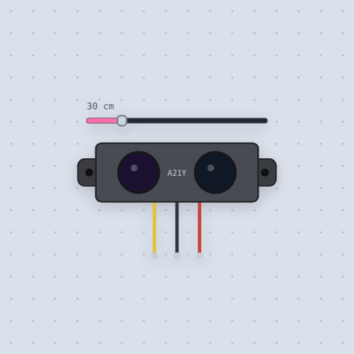
The IR distance sensor, Sharp GP2Y0A21 in brief
What it is, and every setting the properties panel gives it.
The Sharp GP2Y0A21YK0F measures distance by triangulation: an infrared LED throws a spot through one lens and a detector behind the other sees where it lands, so the result is an analog voltage that falls as the object moves away, from about 2.3 volts at 10 centimeters to 0.4 at 80. Its three wires are VO, GND and VCC, and the supply must be 4.5 to 5.5 volts, so even beside an ESP32 it runs from 5 V; the default model’s output stays near 2.3 volts at most, so VO goes straight to an Uno’s A0 or an ESP32 ADC pin. Mokxi fits the inverse curve through the datasheet’s typical points, 33.9 / (d + 4.74) volts, takes a new measurement every 38.3 milliseconds, and reads nothing until the first one after power-up. The model property also offers the GP2Y0A02YK0F, GP2Y0A41SK0F and GP2Y0A710K0F, and the SharpIR library converts to centimeters for the first three. The classic mistake is letting an object come closer than 10 centimeters, where the output falls again and 5 centimeters reads like 25. Part-to-part spread, surface effects and the LED’s current spikes are not modeled.
- Family
- Sensors
- Pins
- 3
- model
- GP2Y0A21YK0F (or GP2Y0A02YK0F, GP2Y0A41SK0F, GP2Y0A710K0F)
- distance
- 30
3 pins
Named as the editor names them, so a wire lands where you expect it.
How to use the Sharp GP2Y0A21 with an Arduino
Wire the red lead (VCC) to 5 V, the black (GND) to GND and the yellow (VO) to A0. The SharpIR library turns the voltage into centimeters: construct it with the model and the pin, then call getDistance(). Outside the 10 to 80 cm range it answers 9 or 81, so treat those two numbers as out of range.
Mount it so nothing can come closer than 10 cm. Below that the output falls again, and a hand pressed against the lenses reads as if it were well away, which is why the rainbow stick in the example never quite fills. Name the same model in the sketch as on the part, or the centimeters come out wrong.
It needs 4.5 to 5.5 V on every board, so beside an ESP32 run it from the 5 V pin; its output stays under the 3.3 V an ESP32 ADC pin can take.
#include <SharpIR.h>
SharpIR sensor(SharpIR::GP2Y0A21YK0F, A0);
void setup() {
  Serial.begin(115200);
}
void loop() {
  Serial.println(sensor.getDistance());
  delay(50);
}What is true about the IR distance sensor, Sharp GP2Y0A21, here
In its help article’s own words: what the simulation gets right, and where it stops.
Modeled
From each model's Sharp datasheet:
| Model | Range | Typical output | Measures every |
|---|---|---|---|
| GP2Y0A21YK0F | 10 to 80 cm | 0.4 V at 80 cm, 2.3 V at 10 | 38.3 ms |
| GP2Y0A02YK0F | 20 to 150 cm | 0.4 V at 150 cm, 2.45 V at 20 | 38.3 ms |
| GP2Y0A41SK0F | 4 to 30 cm | 0.4 V at 30 cm, 2.65 V at 4 | 16.5 ms |
| GP2Y0A710K0F | 100 to 550 cm | 2.5 V at 100 cm, 1.8 V at 200, about 1.35 V at 550 | 16.5 ms |
The curve. The output falls as the inverse of the distance. The model is the
inverse curve through each datasheet's two typical points: 33.9 / (d + 4.74) volts
for the GP2Y0A21YK0F, 62.15 / (d + 5.37) for the GP2Y0A02YK0F and
12.25 / (d + 0.622) for the GP2Y0A41SK0F. The GP2Y0A710K0F's line does not pass
through zero, so it is 1.1 + 140 / d, which meets all three of its typical figures.
Too close. Under the near end the output rises a little and then falls again, so an object too close reads as one further away. On the GP2Y0A21YK0F 5 cm gives about what 25 cm does; the model keeps that trap, though not the exact shape under 10 cm. The other three follow the points of their datasheet's graph: the GP2Y0A41SK0F peaks at 3.04 V at 3 cm, the GP2Y0A02YK0F at 2.75 V at 15 cm, and the GP2Y0A710K0F at 3.09 V at 50 to 60 cm, falling to 1.55 V at 10 cm.
Timing. A new measurement every 38.3 or 16.5 ms by model. The output holds between them, and right after power-up it reads nothing until the first one.
Not modeled
The spread between parts (the far point may be 0.25 to 0.55 V, so calibrate a real one), the small effect of very dark or shiny surfaces, sunlight, the spread of the measuring cycle, and the current spikes of the LED, which is why the datasheets ask for a capacitor across the supply. Under 10 cm the GP2Y0A710K0F's graph stops; the model falls straight to 0 V there.
From IR distance sensor, Sharp GP2Y0A21, in full.
See the IR distance sensor, Sharp GP2Y0A21 in a project
2 built-in projects use it. Each opens in the editor, already wired.
The boards it is shown on
This board has a built-in project with the IR distance sensor, Sharp GP2Y0A21 in it.
The rest of the bench
Every one of these is drawn and simulated the same way.
Wire up the IR distance sensor, Sharp GP2Y0A21
Open the editor and push it into the breadboard. It is free, and it runs on your own machine.