Real-time clock, DS1302
The kit clock with a coin cell: BCD time and 31 bytes of RAM behind CLK, DAT and RST.
- 5 pins
- 2 settings
- In 1 project
- In 1 lesson
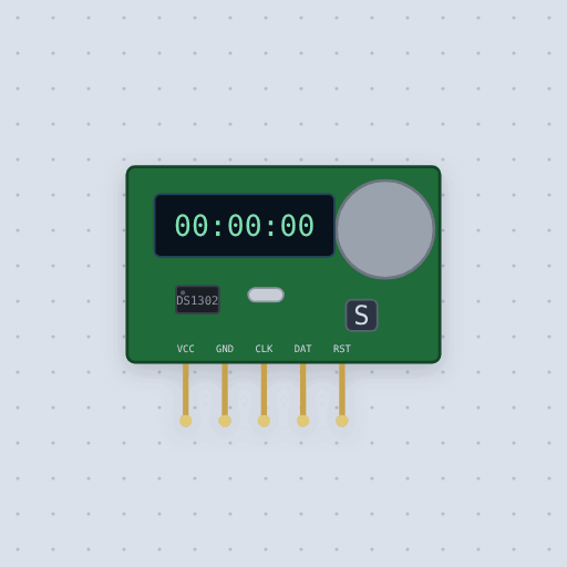
The Real-time clock, DS1302 in brief
What it is, and every setting the properties panel gives it.
The DS1302 is a real-time clock module with a coin cell and a watch crystal. It talks over a three-wire interface of its own: a clock pin, a data line and an enable. It keeps seconds, minutes, hours, date, month, day of the week and year in BCD, plus 31 bytes of RAM. Mokxi models the transfer rules from the datasheet: RST high starts a transfer, a command byte arrives least significant bit first on rising CLK edges, and data comes out on falling edges. Burst mode walks all eight clock registers or all 31 RAM bytes, write protect blocks other writes, and the hours register supports the 12-hour form with a PM bit. Each of the three pins has about 40 kohm pull-downs inside the chip. It does not model the trickle charger, the backup cell, or the undefined state of a new chip. The model starts at the start time with write protect off. Aliases: DS1302, RTC module, three-wire clock.
- Family
- Clocks and links
- Pins
- 5
- start
- 2026-01-01 12:00:00
- halted
- false
5 pins
Named as the editor names them, so a wire lands where you expect it.
How to use the Real-time clock, DS1302 with an Arduino
The example project is "Alarm clock". A DS1302 keeps the time and a TM1637 shows it. At 7:00 a piezo beeps until the button stops it. It runs beside these words, and it opens in the editor as it is drawn here.
The wiring: CLK goes to Arduino Uno pin 5, DAT to pin 4, RST to pin 2, VCC to 5V and GND to GND.
With the default settings, the serial monitor shows "Mokxi Arduino Uno: alarm clock", then "6:59:50", "6:59:51" and "6:59:52". The clock module was set to 6:59:50, so the alarm goes off ten seconds after Run.
Change the setting halted to true and run again. The monitor now shows "Mokxi Arduino Uno: alarm clock", then "clock was stopped: starting it", then "6:59:50", "6:59:51" and "6:59:52". The sketch noticed the halted clock and started it before reading the time.
// Alarm clock: a DS1302 clock module, a TM1637 display, a piezo and a button.
//
//   pins 4, 5, 2  the DS1302's DAT, CLK and RST (ThreeWire's IO, SCLK, CE)
//   pins 7, 6     the TM1637's CLK and DIO
//   pin 8         the piezo; its other leg to ground
//   pin 3         the button, to ground (INPUT_PULLUP: pressed reads LOW)
//
// The display shows the hours and minutes with the colon blinking once a
// second. At 7:00 the alarm beeps in fours until the button is pressed; the
// clock module was set to 6:59:50, so it goes off ten seconds after Run.

#include <ThreeWire.h>
#include <RtcDS1302.h>
#include <TM1637Display.h>

const int PIEZO = 8;
const int BUTTON = 3;
const uint8_t ALARM_HOUR = 7;
const uint8_t ALARM_MINUTE = 0;

ThreeWire myWire(4, 5, 2);
RtcDS1302<ThreeWire> Rtc(myWire);
TM1637Display display(7, 6);

bool ringing = false;
bool doneToday = false;
uint8_t lastSecond = 99;

void setup() {
  Serial.begin(115200);
  Serial.println("Mokxi Arduino Uno: alarm clock");
  pinMode(BUTTON, INPUT_PULLUP);
  display.setBrightness(0x0f);
  Rtc.Begin();
  if (Rtc.GetIsWriteProtected()) Rtc.SetIsWriteProtected(false);
  if (!Rtc.GetIsRunning()) {
    Serial.println("clock was stopped: starting it");
    Rtc.SetIsRunning(true);
  }
}

void loop() {
  RtcDateTime now = Rtc.GetDateTime();
  if (now.Second() != lastSecond) {
    lastSecond = now.Second();
Common Real-time clock, DS1302 errors and fixes
Questions and answers
how do i connect a ds1302 to arduino
Use any three digital pins. In the example, CLK goes to pin 5, DAT to pin 4 and RST to pin 2, plus 5V and GND.
does ds1302 use i2c
No. The DS1302 uses its own three-wire interface with a clock, a data line and an enable. Any three pins will do.
what library for ds1302 arduino
Rtc by Makuna. Include ThreeWire.h and RtcDS1302.h, then write ThreeWire myWire(DAT, CLK, RST); and RtcDS1302<ThreeWire> Rtc(myWire);
why is my ds1302 clock not running
The clock-halt bit may be set. Start it in code with Rtc.SetIsRunning(true), or set halted to false in the editor.
What is true about the Real-time clock, DS1302, here
In its help article’s own words: what the simulation gets right, and where it stops.
Modeled
From the DS1302 datasheet:
The transfer. RST high starts it and low ends it. A command byte comes first,
least significant bit first, each bit taken on a rising edge of CLK; bit 7 must be
1, bit 6 picks RAM, bits 5 to 1 the address and bit 0 a read.
Reads. The data comes out on the falling edges, starting with the falling edge
that ends the command, so a sketch lets go of DAT before then.
Burst mode. Address 31 walks all eight clock registers, or all 31 RAM bytes, in one transfer; a clock burst write is taken only once all eight are in.
Write protect. Bit 7 of the control register, set, blocks every other write.
The hours. Bit 7 of the hours register is the 12-hour form (bit 6 on the DS1307), with bit 5 for PM.
Pull-downs. About 40 kohm on each of the three pins inside the chip.
Not modeled
The trickle charger (its register is stored and read back), the backup cell, and the
undefined state of a brand-new chip: the model starts at start, with write protect
off.
From Real-time clock, DS1302, in full.
See the Real-time clock, DS1302 in a project
One built-in project uses it. It opens in the editor, already wired.
Where it turns up in a lesson
One lesson places it in its own circuit.
The boards it is shown on
This board has a built-in project with the Real-time clock, DS1302 in it.
Keep going
The rest of the bench
Every one of these is drawn and simulated the same way.
Wire up the Real-time clock, DS1302
Open the editor and push it into the breadboard. It is free, and it runs on your own machine.