Two-color LED, KY-011
Red and yellow-green dice under one lens on a shared leg. PWM the two legs for orange and yellow.
- 3 pins
- 1 setting
- In 2 projects
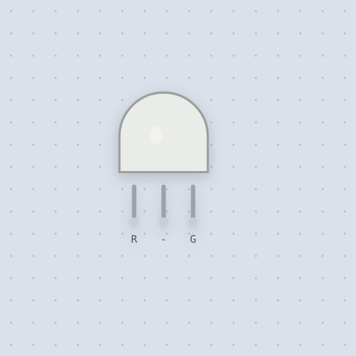
The Two-color LED, KY-011 in brief
What it is, and every setting the properties panel gives it.
The KY-011 is a two-color LED, a red and a yellow-green die under one 5 mm lens with a shared middle leg, the KY-029 at 3 mm. Its legs are R, C and G. On the usual common-cathode part C goes to ground and each colored leg gets its own 220 ohm resistor from a PWM pin, 9 and 10 on an Uno, or any two GPIOs on an ESP32, where 3.3 volts still lights both dice with less current. Lighting both mixes orange and yellow, so analogWrite() walks the color between red and green. Mokxi models each die as its own LED, 2.0 volts for the 644 nanometer red and 2.2 for the 571 nanometer green, about 13.4 and 12.5 milliamps through 220 ohms from 5 volts, with an 8 millisecond eye average that turns PWM into a mixed color. The common property switches to common anode, where a low leg lights. The classic mistake is one resistor in the common leg, so the two dice share its current and turning one off brightens the other; the modules have no resistors on board either. The two-lead bipolar kind, reverse breakdown and heat are not modeled.
- Family
- Outputs
- Pins
- 3
- common
- cathode (or anode)
cathode(the usual part, and the KY-011's), whereCgoes to ground and a high leg lights its die, oranode, whereCgoes to the supply and a low leg lights.
3 pins
Named as the editor names them, so a wire lands where you expect it.
How to use the KY-011 two-color LED with an Arduino
The middle leg, C, goes to ground; R goes to PWM pin 9 and G to PWM pin 10, each through its own 220 ohm resistor. The KY-011 module has none on board. Light both dice and the lens glows orange or yellow, so analogWrite() on the two pins walks the color from red to green.
The level light here reads a knob on A0: below halfway the red die stays full and the green one comes up, above halfway the green stays full and the red goes down. Put one resistor in the common leg instead of two and the dice share its current, so turning one off brightens the other.
On an ESP32 any two GPIOs do, with analogWrite() or ledcWrite(); 3.3 V still lights both dice, with less current through the same 220 ohm.
int level = analogRead(A0);  // 0 to 1023
int red = level < 512 ? 255 : (1023 - level) / 2;
int green = level < 512 ? level / 2 : 255;
analogWrite(RED_PIN, red);
analogWrite(GREEN_PIN, green);What is true about the Two-color LED, KY-011, here
In its help article’s own words: what the simulation gets right, and where it stops.
Modeled
Two dice, two currents. Each die is the same Shockley-equation LED as the LED, conducting on its own between its leg and the common, so one die on does not change the other's current.
The drops of this part. The KY-011 sheet gives 644 nm red and 571 nm green, both at 2.0 to 2.5 V and 20 mA. 571 nm is the yellow-green GaP die, not the 3 V InGaN green of a modern single-color LED, so the model uses 2.0 V for red and 2.2 V for green. On 220 ohm from 5 V they run at about 13.4 and 12.5 mA, nearly even, which is why one resistor value suits both legs here when it does not on an RGB LED.
Perceived color. The brightness is an 8 ms average, the plain LED's, so PWM reads as the mixed color rather than a flicker between red and green.
Not modeled
The two-lead bipolar kind, whose two dice sit back to back across two legs and change color with the direction of the current. Reverse breakdown, heat, and the small differences in brightness between a red and a green die at the same current: here 20 mA is full brightness for either.
From Two-color LED (KY-011), in full.
See the Two-color LED, KY-011 in a project
2 built-in projects use it. Each opens in the editor, already wired.
The boards it is shown on
This board has a built-in project with the Two-color LED, KY-011 in it.
The rest of the bench
Every one of these is drawn and simulated the same way.
Wire up the Two-color LED, KY-011
Open the editor and push it into the breadboard. It is free, and it runs on your own machine.