Biaxial stepper
Two steppers on one axis, a hand each, like a clock: two pairs of coils, 200 steps a turn.
- 8 pins
- 6 settings
- In 1 project
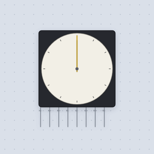
The Biaxial stepper in brief
What it is, and every setting the properties panel gives it.
A biaxial stepper is two bipolar stepper motors on one axis, one shaft inside the other, so one body can turn two hands like a clock. It is also called a dual shaft stepper, a coaxial stepper, or a clock stepper. The A1 and B1 pins serve the outer hand's motor, the A2 and B2 pins the inner hand's. Each motor is modeled the same way as a NEMA 17: two coil currents point a field, the rotor follows it the short way around at up to max_steps full steps per second, slips a whole electrical cycle when driven faster, and holds nothing below 5 percent of its rated current. Settings per motor include resistance of 1.5 ohms a coil, current of 1.7 A, 200 steps a turn, and the starting angle of each hand. The model leaves out inductance, back EMF, torque, load, and resonance. Real dual-shaft gauge motors have their own gearing, so set steps to match.
- Family
- Outputs
- Pins
- 8
- resistance
- 1.5
- current
- 1.7
- steps
- 200
- max_steps
- 1000
- angle
- 0
- inner_angle
- 0
8 pins
Named as the editor names them, so a wire lands where you expect it.
How to use the biaxial stepper with an Arduino Uno
The Two hands project turns a biaxial stepper into a clock. Two A4988 boards drive it, one per hand. The outer motor's pins A1+, A1-, B1+ and B1- go to the first driver's 2B, 2A, 1A and 1B pins. The inner motor's pins A2+, A2-, B2+ and B2- go to the second driver's matching pins. Both drivers have VMOT on 12 V, VDD on 5 V, RST linked to SLP, the mode pins left low for full step, and the grounds tied to the Uno's. Each hand then gets its own STEP and DIR signal: pins 3 and 4 for the outer, minutes hand, and pins 5 and 6 for the inner, hours hand.
The sketch runs a minute every second so the motion can be watched. A 200-step hand should turn once in 60 minutes for the outer hand and once in 12 hours for the inner, which works out to m x 200 / 60 and m x 200 / 720 steps after m minutes. Neither count is a whole number per minute, so the sketch keeps a running tally of the steps it owes each hand and pulses STEP until the debt is paid, the way a Bresenham line keeps its error. After paying, it prints the time as hours and minutes, with the minutes zero padded, and waits a second.
With default settings, the serial monitor printed: "Two hands: a minute a second", "0:01" and "0:02". The first line is the banner from setup. Each later line is the clock as hours, a colon and minutes, and one printed minute passes each second.
Things to try: raise steps to match a geared dual-shaft gauge motor, set a different starting angle and inner_angle to see where the hands begin, or swap the two motors' wires and watch the hour hand race round like a minute hand.
// Two hands: a biaxial stepper is a clock face's movement, two motors on
// one axis, driven here through two A4988s in full step, a minute every
// second so it can be watched.
//
//   pin 3  outer hand's STEP   pin 4  its DIR    (the minutes)
//   pin 5  inner hand's STEP   pin 6  its DIR    (the hours)
//   both drivers: VMOT on 12 V, VDD on 5 V, RST linked to SLP, the mode pins
//   left low (full step), the grounds to the Uno's
//
// 200 full steps turn a hand once. The minute hand goes round in 60 minutes
// and the hour hand in 12 hours, so after m minutes they should have taken
// m x 200 / 60 and m x 200 / 720 steps. Neither is a whole number per
// minute, so the sketch keeps the count it owes each hand and steps until
// it has paid it, the way a Bresenham line keeps its error.

const int STEP_OUTER = 3;
const int DIR_OUTER = 4;
const int STEP_INNER = 5;
const int DIR_INNER = 6;

long minutes = 0;
long outerSteps = 0;
long innerSteps = 0;

void pulse(int pin) {
  digitalWrite(pin, HIGH);
  delayMicroseconds(5);
  digitalWrite(pin, LOW);
  delay(3);
}

void setup() {
  Serial.begin(9600);
  pinMode(STEP_OUTER, OUTPUT);
  pinMode(DIR_OUTER, OUTPUT);
  pinMode(STEP_INNER, OUTPUT);
  pinMode(DIR_INNER, OUTPUT);
  digitalWrite(DIR_OUTER, HIGH);
  digitalWrite(DIR_INNER, HIGH);
  Serial.println("Two hands: a minute a second");
}

void loop() {
  minutes++;
  while (outerSteps < minutes * 200 / 60) {
Common Biaxial stepper errors and fixes
Questions and answers
what is a biaxial stepper
Two bipolar stepper motors on one axis, one shaft inside the other, so one body turns two hands like a clock. It is also called a dual shaft or coaxial stepper.
how do you drive a biaxial stepper
Each motor wants its own pair of H-bridges: two A4988 or DRV8825 boards, or an L298N each in full step. Then it is STEP and DIR per hand.
what are the biaxial stepper's coil resistance and current
Per motor, the same as a NEMA 17: resistance is 1.5 ohms a coil and current is rated 1.7 A.
does the biaxial stepper model torque
No. The model leaves out inductance, back EMF, torque, load, and resonance. The rotor follows the coil field the short way and slips a whole electrical cycle only when driven faster than max_steps.
What is true about the Biaxial stepper, here
In its help article’s own words: what the simulation gets right, and where it stops.
Modeled
Each motor is the NEMA 17 model on its own four wires: the two coil currents point
a field, the rotor follows it the short way around at up to max_steps, slips a
whole electrical cycle when driven faster, and holds nothing below 5% of its rated
current.
Not modeled
What the NEMA 17 leaves out: inductance, back EMF, torque and load, and resonance.
The small dual-shaft gauge motors this stands for have gearing of their own; set
steps to match.
From Biaxial stepper, in full.
See the Biaxial stepper in a project
One built-in project uses it. It opens in the editor, already wired.
The boards it is shown on
This board has a built-in project with the Biaxial stepper in it.
The rest of the bench
Every one of these is drawn and simulated the same way.
Wire up the Biaxial stepper
Open the editor and push it into the breadboard. It is free, and it runs on your own machine.