Self-balancing robot
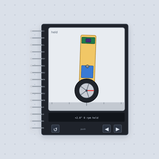
An inverted pendulum on two wheels, with its own MPU6050 and TB6612. Let go and it falls, unless your loop drives the wheels under it.
- 15 pins
- 20 settings
- In 1 project
- In 1 lesson
The Self-balancing robot in brief
What it is, and every setting the properties panel gives it.
The self-balancing robot is a two wheel robot that falls over unless your code balances it: the body of the balance car kits, with its own MPU6050, TB6612 driver and Hall encoders. VCC and GND power the logic from 2.7 V to 5.5 V and the motors run from the robot’s own battery. SCL and SDA are the MPU6050 at 0x68. STBY is the driver’s standby, high to run, and has a 200 k pull-down so unwired it is off. AIN1, AIN2 and PWMA drive the left motor and BIN1, BIN2 and PWMB the right, with the TB6612 truth table. LA, LB, RA and RB are optional quadrature encoders. Let go of it and it is an inverted pendulum, and only the sketch drives the wheels.
- Family
- Outputs
- Pins
- 15
- mass
- 800
- com
- 70
- inertia
- 17
- height
- 160
- wheel
- 68
- wheel_mass
- 40
- voltage
- 7.4
- battery
- 7.4
- rpm
- 280
- stall
- 4
- rotor
- 4
- ratio
- 30
- ppr
- 13
- friction
- 20
- damping
- 0.5
- imu
- 120
- noise
- 1
- gyro_bias
- 0
- tilt
- 2
- release
- 1000
15 pins
Named as the editor names them, so a wire lands where you expect it.
How to build a self balancing robot with an Arduino and a PID
The robot carries its own MPU6050 and TB6612, so the Uno only wires to it. The IMU’s bus is on pins 12 (SCL) and 2 (SDA), a second software I2C bus apart from the OLED’s on A5 and A4. The driver’s direction pins are 10 and 9 for the left motor and 5 and 4 for the right, and the PWM pins are 6 and 3. STBY goes to 5 V, and so does the robot’s VCC.
Every 10 ms the sketch blends the gyro and the accelerometer into a tilt with a complementary filter, 0.98 of the integrated gyro and 0.02 of the angle from gravity, runs a PID on it and drives both wheels. Three knobs on A0, A1 and A2 set Kp, Ki and Kd while it runs, and the OLED shows the angle and the gains. The robot is held for its first second, then let go. Push it with the arrows on its window and watch it catch itself; turn Ki to zero and watch it creep off and fall.
Common Self-balancing robot errors and fixes
Questions and answers
Why not trust the accelerometer alone?
It feels the robot accelerating as well as gravity, exactly as a real one does, so balancing code blends it with the gyroscope.
What does each PID gain do on a balancing robot?
Kp pushes back in proportion to the tilt, Ki removes a steady lean and Kd damps the swing. With Ki at zero the robot creeps off and falls.
Does the robot have wheel encoders?
Yes. LA, LB, RA and RB are the two quadrature encoders, optional: leave them unwired if you do not count them.
What is true about the Self-balancing robot, here
In its help article’s own words: what the simulation gets right, and where it stops.
Not modeled
Turning: the two wheels share one axle, so their torques add and a difference
between them does not yaw the robot. Wheel slip, an uneven floor, gearbox backlash,
motor inductance, the driver's half ohm and current limit, the battery sagging or
running down, and the MPU6050's INT pin, DMP and FIFO.
From Self-balancing robot, in full.
See the Self-balancing robot in a project
One built-in project uses it. It opens in the editor, already wired.
Where it turns up in a lesson
One lesson places it in its own circuit.
The boards it is shown on
This board has a built-in project with the Self-balancing robot in it.
The rest of the bench
Every one of these is drawn and simulated the same way.
Wire up the Self-balancing robot
Open the editor and push it into the breadboard. It is free, and it runs on your own machine.