Arcade joystick lever
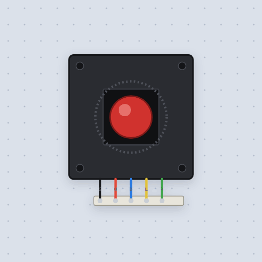
The Sanwa JLF style lever: four microswitches to a common GND. Drag the ball, or use the arrow keys or W A S D.
- 5 pins
- 2 settings
- In 1 project
The Arcade joystick lever in brief
What it is, and every setting the properties panel gives it.
The arcade lever is a fight stick’s Sanwa JLF style stick: a ball top on a shaft with four microswitches around its foot, read with digitalRead() rather than analogRead(). Its five-pin harness is GND, the common, then UP, DOWN, LEFT and RIGHT, each closed to GND while its direction is held, and two at once in a corner. With no supply pin it suits any board: on an Uno, GND to GND and the four switches to pins 5, 4, 3 and 2 with INPUT_PULLUP; on an ESP32, any four GPIOs with their pull-ups on. Mokxi models the four contacts and the shaft: opposed directions never close together and the newer push wins, and the gate property picks the square plate, the octagon (electrically the same) or a 4-way plus with no corners. The bounce property makes each switch chatter once inside 2 milliseconds. Drag the ball, or use the arrow keys or W A S D. The classic mistake is leaving out INPUT_PULLUP, so a released direction floats. The spring’s feel, the engage distance and the throw are not modeled; the lever is in a direction or it is not.
- Family
- Inputs
- Pins
- 5
- gate
- square (or octagon, 4way)
- bounce
- false
5 pins
Named as the editor names them, so a wire lands where you expect it.
GND while the lever is up, up-left or up-right.GND while the lever is down or in a lower corner.GND while the lever is left or in a left corner.GND while the lever is right or in a right corner.How to use an arcade joystick lever with an Arduino
The harness is five wires: GND to GND, and UP, DOWN, LEFT and RIGHT to pins 5, 4, 3 and 2 with INPUT_PULLUP. Each pin reads LOW while its direction is held, and a corner holds two. It is four switches, so read it with digitalRead(), not analogRead().
The sketch here takes each new reading at once and then ignores that switch for 5 ms, the way a stick board debounces, and prints the direction in numpad notation: 5 neutral, 8 up, 9 up-right. Turn on the lever’s bounce property and it still prints one line per move. Set the gate to 4way and the corners are gone.
The lever has no supply pin, so on an ESP32 it takes any four GPIOs with their pull-ups on.
What is true about the Arcade joystick lever, here
In its help article’s own words: what the simulation gets right, and where it stops.
Modeled
Four contacts and a common. A closed switch is a low-resistance contact from its
pin to GND, passing current either way; an open one leaves its pin floating, so
without a pull-up the pin reads nothing useful, as on the real harness.
The shaft cannot be on both sides. Up and down are never closed together, and neither are left and right. If both of an opposed pair are pushed at once (two keys held), the newer one wins, the way the shaft swings over. A fight stick firmware's SOCD cleaning still matters for a hitbox, where four separate buttons can all be down; it does not for a lever.
The 4-way plate. With the lever in one arm of the plus, pushing the other axis too does nothing: the only way into the other arm is back through the center.
Bounce, when it is on: one make, one rebound, one settle per switch that moves, the pattern a snap-action microswitch shows on a scope.
Not modeled
The spring's feel, the engage distance and the throw: the lever is either in a direction or not. Square and octagon gates differ only in the picture. The microswitch's bounce, when on, is the same fixed pattern every time.
From Arcade joystick lever, in full.
See the Arcade joystick lever in a project
One built-in project uses it. It opens in the editor, already wired.
The boards it is shown on
This board has a built-in project with the Arcade joystick lever in it.
The rest of the bench
Every one of these is drawn and simulated the same way.
Wire up the Arcade joystick lever
Open the editor and push it into the breadboard. It is free, and it runs on your own machine.