LED arcade button
The cabinet button with a lamp inside: the switch on two tabs, a 5 V or 12 V LED on the other two.
- 4 pins
- 6 settings
- In 1 project
- In 1 lesson
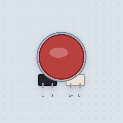
The LED arcade button in brief
What it is, and every setting the properties panel gives it.
The LED arcade button is a 30 mm arcade button with a lamp inside: a microswitch on tabs 1 and 2, and an LED with its resistor in the holder on L+ and L-. Pressing it does not light it; the sketch decides. On an Uno, tab 1 goes to GND and tab 2 to an input with INPUT_PULLUP, so a press reads LOW, and a 5 V lamp goes straight from a PWM pin to ground, a red one drawing about 19 milliamps. On an ESP32 the switch wires the same, but a 5 V lamp on a 3.3 volt pin runs at about half its current. Mokxi models the lamp as the color’s LED in series with the holder’s 150 ohms for a 5 V lamp or 470 ohms for a 12 V one, so a white or blue lamp is dimmer than a red one on the same supply, and the bounce property adds one rebound inside 2 milliseconds The classic mistake is a 12 V lamp on a 5 V pin, which barely glows: switch its L- with a transistor from 12 volts. Bare lamps with no resistor, and heat, are not modeled.
- Family
- Inputs
- Pins
- 4
- color
- red (or green, blue, yellow, white)
- lamp
- 5V (or 12V)
- bounce
- false
- size
- 30 (or 24)
- label
- key
4 pins
Named as the editor names them, so a wire lands where you expect it.
How to use an LED arcade button with an Arduino
It is two parts in one housing. The microswitch: tab 1 to GND and tab 2 to pin 7 with INPUT_PULLUP, so a press reads LOW. The lamp: L+ to PWM pin 5 and L- to ground. A 5 V lamp has its resistor in the holder, so it goes straight on a pin, and a red one draws about 19 mA.
Pressing the button does not light it; the sketch decides. The lit button here breathes the lamp with analogWrite() while it waits, goes full bright while held, and counts every press. A 12 V lamp on a 5 V pin barely glows: switch its L- with a transistor from a 12 V supply instead.
On an ESP32 the switch wires the same; a 5 V lamp on a 3.3 V pin runs at about half its current, and a white or blue one barely lights.
What is true about the LED arcade button, here
In its help article’s own words: what the simulation gets right, and where it stops.
Modeled
The lamp is the bench's LED model for its color in series with the holder's resistor, so it is a diode: wired the wrong way it stays dark, a white or blue lamp drops a volt more than a red one and is dimmer on the same supply, and a 12 V lamp on 5 V barely glows. The switch is the arcade button's microswitch.
Not modeled
Lamps with no resistor (the bare LED kind), and heat.
From LED arcade button, in full.
See the LED arcade button in a project
One built-in project uses it. It opens in the editor, already wired.
Where it turns up in a lesson
One lesson places it in its own circuit.
The boards it is shown on
This board has a built-in project with the LED arcade button in it.
The rest of the bench
Every one of these is drawn and simulated the same way.
Wire up the LED arcade button
Open the editor and push it into the breadboard. It is free, and it runs on your own machine.