APA102 (DotStar) LED strip
Addressable LEDs with a clock: any speed works, and each LED has a 5-bit brightness on top of its color.
- 6 pins
- 1 setting
- In 1 project
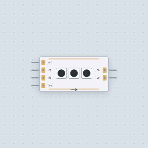
The APA102 (DotStar) LED strip in brief
What it is, and every setting the properties panel gives it.
The APA102, also sold as DotStar, SK9822 or APA102C, is an addressable RGB LED strip with both a data wire and a clock wire. Each LED reads the data line on the rising edge of the clock, so the board sets the pace: a slow digitalWrite() loop, hardware SPI, or an interrupt in the middle of a frame all work, unlike a WS2812 whose bits must be timed to a fraction of a microsecond. Each LED frame is 32 bits: 111, a 5-bit global brightness in 31 steps, then blue, green and red, 8 bits each, most significant bit first. The count setting sets how many LEDs the strip has, 1 to 1024. The model shows each LED's average color, not the PWM flicker underneath, and the strip draws no current, where a real one pulls up to about 60 mA an LED at full white. No maximum clock rate is enforced because the datasheet gives none.
- Family
- Outputs
- Pins
- 6
- count
- 8
6 pins
Named as the editor names them, so a wire lands where you expect it.
CI.DI.How to use the APA102 (DotStar) strip with an Arduino
The DotStar rainbow project runs a 30-LED APA102 strip on an Arduino Uno R3. A rainbow flows along the strip while the Serial Monitor reports how long each show() takes. The strip's VCC goes to the Uno's 5V pin through the breadboard power rail, GND to the Uno's GND pin the same way, DI to pin 4, and CI to pin 5. The part's count setting is set to 30 LEDs.
The sketch uses the Adafruit_DotStar library and makes the strip with Adafruit_DotStar strip(LEDS, DATA_PIN, CLOCK_PIN, DOTSTAR_BGR). DotStar_BGR is the datasheet's blue, green, red order; some real strips are wired the other way, but on this part DOTSTAR_BRG swaps red and green. In loop() the sketch calls strip.rainbow(first) to spread one turn of the color wheel over the strip, times strip.show() with micros(), advances the hue by SPEED, and every 50 frames prints the show() time.
With default settings, the serial monitor printed: "DotStar rainbow: 30 LEDs on pins 4 (data) and 5 (clock)" then "show() took 18488 us" and "show() took 18364 us". The first line confirms the pin wiring at startup, and the numbers are how many microseconds each show() needed to clock a full frame out to all 30 LEDs.
Things to try: change SPEED, which is how far the hue moves each frame, or change the brightness. You can also make the strip with no pins, Adafruit_DotStar strip(LEDS, DOTSTAR_BGR), and wire DI to pin 11 (MOSI) and CI to pin 13 (SCK): hardware SPI sends the same frames much faster, and the show() time drops.
// DotStar rainbow: a rainbow flows along a 30-LED APA102 (DotStar) strip,
// and the Serial Monitor shows how long each show() takes.
//
//   strip   APA102 strip, 30 LEDs: DI <- pin 4, CI <- pin 5, VCC to 5V, GND
//
// An APA102 has a clock wire as well as a data wire. The LED reads the data
// on every rising edge of the clock, so it does not care how fast or slow the
// edges come: a plain digitalWrite() loop is fine, and so are interrupts in
// the middle of a frame. A WS2812 needs its bits timed to a fraction of a
// microsecond instead.
//
// What show() sends, 32 bits at a time:
//   start frame   32 zeros
//   each LED      111, a 5-bit global brightness, then blue, green and red
//   end frame     ones, one clock for every two LEDs, to push the last
//                 frames down the strip (each LED delays the data half a clock)
//
// The colors go out blue first, so the strip is made with DOTSTAR_BGR, the
// order in the APA102 datasheet.
//
// Things to try. Change SPEED. Change the brightness. Make the strip with no
// pins, Adafruit_DotStar strip(LEDS, DOTSTAR_BGR), and wire DI to pin 11
// (MOSI) and CI to pin 13 (SCK): hardware SPI sends the same frames much
// faster, and the show() time drops.

#include <Adafruit_DotStar.h>
#include <SPI.h>

const int LEDS = 30;
const int DATA_PIN = 4;
const int CLOCK_PIN = 5;
const uint16_t SPEED = 512;  // how far the hue moves each frame, of 65536

Adafruit_DotStar strip(LEDS, DATA_PIN, CLOCK_PIN, DOTSTAR_BGR);

uint16_t first = 0;
unsigned long frames = 0;

void setup() {
  Serial.begin(9600);
  strip.begin();
  strip.setBrightness(96);
  strip.show();  // every LED off
  Serial.println("DotStar rainbow: 30 LEDs on pins 4 (data) and 5 (clock)");
}
Common APA102 (DotStar) LED strip errors and fixes
Questions and answers
what is the apa102 led strip
An addressable RGB LED strip with a clock wire and a data wire, also sold as DotStar, SK9822 or APA102C. Each LED reads the data line on the rising edge of the clock, so any speed works.
how many leds can the apa102 strip have
The count setting sets the number of LEDs, from 1 to 1024.
what order are the apa102 colors
Blue, green, red, most significant bit first, per the datasheet. Use DOTSTAR_BGR with the Adafruit_DotStar library.
how do i chain apa102 strips
Wire the first strip's CO to the next strip's CI, and DO to the next strip's DI.
What is true about the APA102 (DotStar) LED strip, here
In its help article’s own words: what the simulation gets right, and where it stops.
Not modeled
The LEDs show their average color, not the PWM flicker underneath. A frame whose first
three bits are not 111 is ignored (the datasheet's self-detection mode). No maximum
clock rate is enforced, because the datasheet gives none; real strips run at 1 to 10
MHz and long ones want slower. The strip draws no current from the supply, where a real
one pulls up to about 60 mA an LED at full white.
From APA102 (DotStar) LED strip, in full.
See the APA102 (DotStar) LED strip in a project
One built-in project uses it. It opens in the editor, already wired.
The boards it is shown on
This board has a built-in project with the APA102 (DotStar) LED strip in it.
Arduino libraries for the APA102 (DotStar) LED strip
Built in, so the sketch compiles with nothing to install. Each page has the calls, the wiring and an example to run.
Keep going
The rest of the bench
Every one of these is drawn and simulated the same way.
Wire up the APA102 (DotStar) LED strip
Open the editor and push it into the breadboard. It is free, and it runs on your own machine.