ESP32-S3-CAM simulator, the camera board on the ESP32-S3
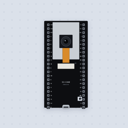
The ESP32-S3-CAM is the common ESP32-S3 camera dev board: an ESP32-S3-WROOM-1 with 8 MB of PSRAM, an OV2640 camera socket, USB-C and a BOOT button, on forty-four header pins named by GPIO. Its user LED is on GPIO 48, and WiFi joins a simulated network. The camera is drawn but not simulated: esp_camera_init() fails and says so. A sketch can be as big as the Arduino IDE allows, 1,310,720 bytes, because it runs from flash as it does on the real board.
- 6peripheral areas modeled
- 1project ready to run
- Real timeon your own machine
What is modeled
Taken from the board's own contract document and put in plain words, with what is missing beside it.
Modeled
- Core
- One Xtensa LX7 core, the ESP32-S3 DevKitC-1 model whole
- Flash
- 1,310,720 bytes for the sketch, as the Arduino IDE’s default partition gives it
- GPIO
- Every pin on the headers, numbered as the silkscreen numbers it
- The user LED
- GPIO 48, lit when the pin is HIGH, as LED_BUILTIN
- UART0
- TX and RX, wired to the serial monitor
- WiFi, simulated
- WiFi.h over a network written in software: no radio, no 802.11, and real internet only when you sign in and switch it on
Not modeled
- The OV2640 camera: its pins are ordinary GPIOs here and no image comes from it. esp_camera_init() returns ESP_ERR_NOT_FOUND and says why.
- The 8 MB of PSRAM, and the microSD slot.
- The second core, USB, I2S and the radio’s Bluetooth.
Open one and press Run
Each of these opens in the editor exactly as it is drawn here.
Questions
Is it free?
Yes. Every board and every part is on the free plan, with no account needed.
Does the camera work?
No. The camera is drawn, but nothing simulates it, so esp_camera and its image never arrive; init fails with a message that says so. Everything else on the board does run.
Is it the same as the ESP32-S3 DevKitC-1?
Same chip, same firmware and the same header, on a camera board with PSRAM.
The other boards
Every one of these runs today, and every one is free.
A RISC-V chip at 160 MHz, on the real memory map.
The classic Arduino, with an ATmega328P running at 16 MHz.
The Uno’s chip on a small board that fits a breadboard.
The big Arduino, with 54 digital pins and four serial ports.
An Uno-shaped board whose chip does its own USB serial.
A second RISC-V board, with 31 pins and simulated WiFi.
The classic ESP32 at 240 MHz, with simulated WiFi.
The ESP32-S3 at 240 MHz, with USB serial and an RGB LED.
Try it on your own firmware
What you build here runs on the board on your desk, unchanged. Nothing to install and no account needed.